OrangePi RV2 Overclocking Update
In this blog post I provide an update on my progress trying to overclock the OrangePi RV2 single board computer.
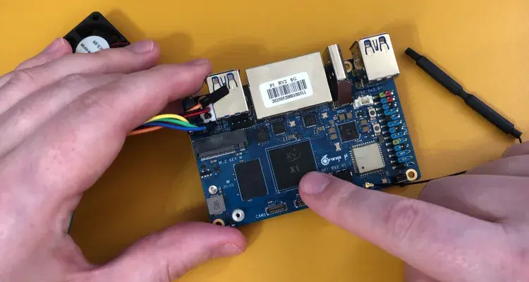
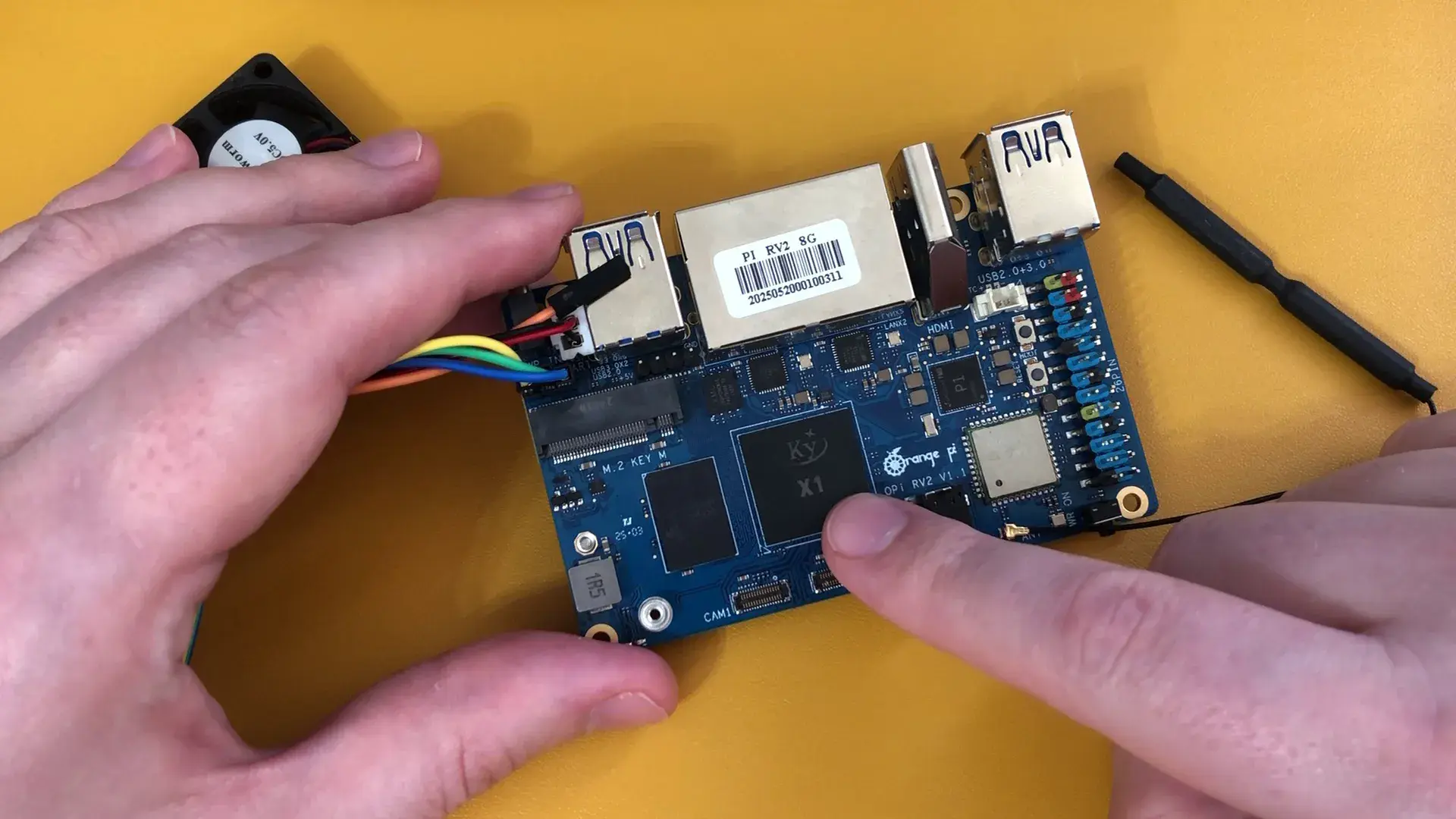
OrangePI sent me this OrangePi RV2 8GB SBC after seeing my overclocking exploits with the OrangePi 5 Max 16GB from a couple of months ago. The RV2 features an 8-core RISC-V SoC in the form of the Ky X1 which is actually a re-branded SpaceMit K1 SoC.
Since I had never tried a Risc-V based SoC, I figured this would make for a nice winter project. I hoped to finish the SkatterBencher guide by the end of the year. But things took a lot longer to progress than I had hoped. In short: I still don’t have enough material to put together an overclocking guide, so in this video I want to give you an update on where I’m at and what I’ve done so far.
Preparing for an Overclocking Guide
The key requirement for a SkatterBencher overclocking guide is path-finding for maxing out a chip’s performance. Typically, that requires a couple of things:
- Tools for monitoring telemetry,
- Tools for adjusting the clock frequencies, and
- Tools for adjusting the voltages.
On X86 platforms, usually these tools are provided for in the form of HWiNFO support, BIOS options, and sometimes custom tuning tools like Shamino’s OC Pack. For SBCs, these are usually less common. For example, for Raspberry Pi 5 and OrangePi 5 Max I ended up creating my own tools.
The same applies to RV2: there’s not that much support out there currently, so we end up having to put together our own tools. Let me walk you through what I have so far.
OrangePi RV2 Telemetry
When it comes to telemetry, our needs are two-fold: we want a tool that informs us about the telemetry right here, right now; and we want to export the telemetry to CSV for further analysis.
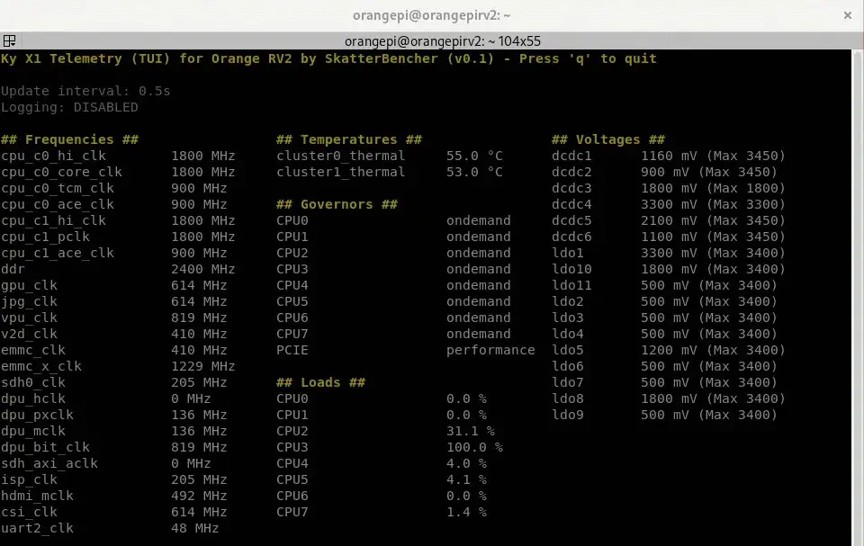
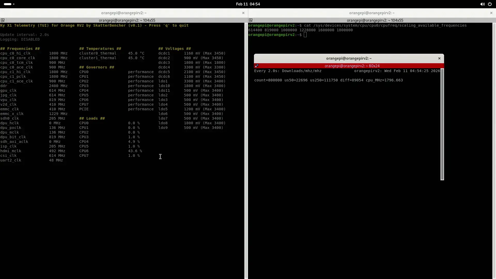
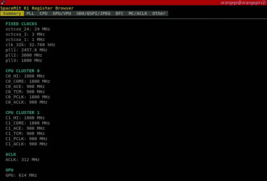
The telemetry tool I built for the OrangePi RV2 is very similar to that of the OrangePi 5. Everything is read directly from existing Linux kernel subsystems and hardware-facing interfaces. That includes the operating frequencies, temperatures, and voltages, as well as CPU usage and performance governors.
GitHub link: https://github.com/SkatterBencher/orangepi-rv2-tools/tree/main/rv2-telemetry-tui
Below are a breakdown of the telemetry domains and their exact sources.
- Operating Frequency: /sys/kernel/debug/clk/clk_summary
- Operating Voltage: /sys/class/regulator/regulator.*
- Operating Temperature: /sys/class/hwmon/hwmon*/
- CPU Usage: Source: /proc/stat
- Performance Governors:
- CPU: /sys/devices/system/cpu/cpu*/cpufreq/scaling_governor
- PCIE: / sys/module/pcie_aspm/parameters/policy
The information provided from the clock summary provides the information as configured by the Linux kernel but not necessarily the actual clock frequency. I’ll get back to that later in the video.
OrangePi RV2 Performance Governors
The first step in my SkatterBencher guides is always setting the performance governors to maximum performance. Just like we did with the OrangePi 5 Max, on the RV2 we can easily do this with a startup file:
Location: /bin/opirv2perf

echo powersave | tee /sys/devices/system/cpu/cpu*/cpufreq/scaling_governor
echo performance | tee /sys/module/pcie_aspm/parameters/policy
echo performance | tee /sys/devices/system/cpu/cpu*/cpufreq/scaling_governor
For some strange reason I need to first switch the CPU cores to powersave before fixing to performance mode. If I don’t do this then it won’t stick to performance.
Then we can easily enable this startup file with a service.
Location: /etc/systemd/system/opirv2perf.service

[Unit]
Description=Set all governors to Performance
After=multi-user.target
Requires=multi-user.target

[Service]
Type=oneshot
ExecStart=/bin/bash /bin/opirv2perf
User=root
Group=root
RemainAfterExit=yes

[Install]
WantedBy=multi-user.target
GitHub link: https://github.com/SkatterBencher/orangepi-rv2-tools/tree/main/rv2-perf-governors
Enable Service:
To enable service: sudo systemctl enable opi5perf.service
To start service: sudo systemctl start opi5perf.service
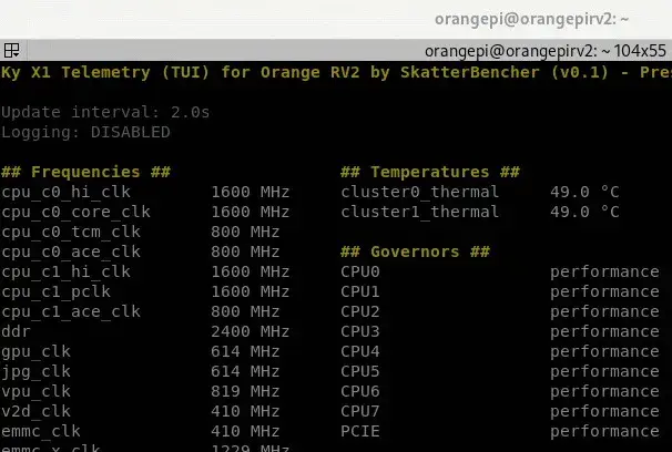
To disable service: sudo systemctl disable opi5perf.serviceAfter locking the CPU governors to performance, you’ll find the CPU frequency locked in at 1.6 GHz.
OrangePi RV2 Voltage Tuning
The next step in preparing for the SkatterBencher overclocking guide is enabling overvolting. This will be important when we later try overclocking.
SpaceMit Power Stone P1 PMIC
The OrangePi RV2 uses the SpaceMit Power Stone P1 PMIC. This PMIC offers 6 buck convertors with voltage support from 0.5V to 3.4V, and 12 programmable LDO regulators. It also has an I2C interface which will come in handy for adjusting the voltages at runtime.
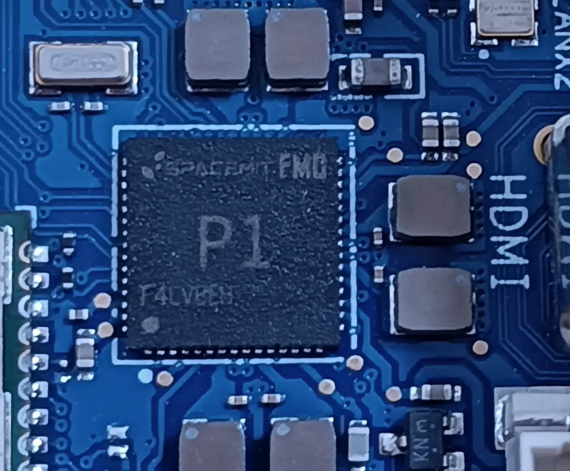
The cool thing about the SpaceMit P1 is that it’s very well documented on the SpaceMit website. There’s even a full English description of the PMIC registers! That means, in theory, we’d be able to gain full, external control over the PMIC.
In theory, there are three ways we can adjust the operating voltage.
- We can adjust the voltages in the device tree binary, which the kernel then relies upon to configure the device at runtime. In the OrangePi 5 Max guide, that’s how we increased the voltage for the CPU cores and GPU, for example.
- Sometimes, we can gain control via software and communicate via the I2C interface.
- Lastly, as we did in the Raspberry Pi 5 guide, we can gain control via the hardware itself and hook up, for example, an ElmorLabs EVC2 to the I2C pins (SCL=45, SDA=44) or manipulate the feedback circuit.
The preferred method is option 2: via software access. That’s because it would allow us to adjust the voltage at runtime, unlike option 1, and we wouldn’t need to solder anything, unlike option 3.
Now, option 2 isn’t straight-forward because the PMIC is actually in use by the kernel to dynamically adjust the voltage according to the DVFS or OPP frequency tables. So, with the Raspberry Pi 5 I ended up using the ElmorLabs EVC2 and for the OrangePi 5 Max I ended up adjusting the voltages in the device tree binary. That’s mainly because I thought it wasn’t possible to gain control over the PMIC I2C at runtime.
However, that turned out not to be true.
SpaceMit P1 PMIC TUI
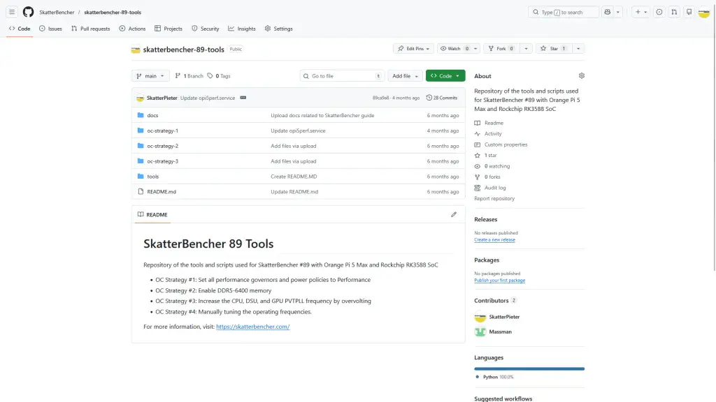
In a comment on my RK3588 GitHub repo, SBC enthusiast hbiyik mentioned how they implemented VR control for the RK806 regulator used on the Orange Pi 5 Max.
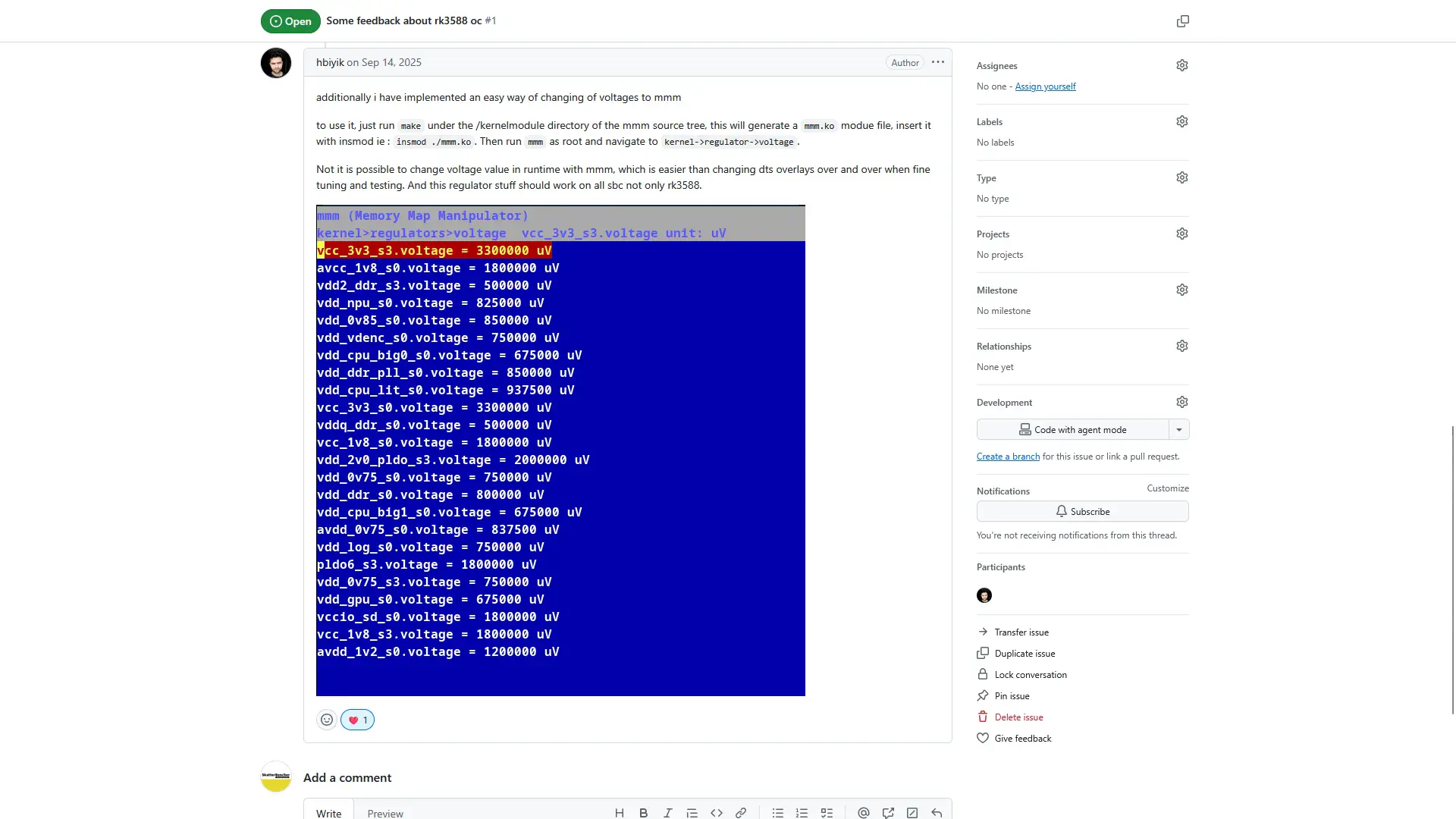
Since that’s possible, I wanted to see if it was possible for the RV2 as well. Now I won’t pretend to know how everything works exactly, but the long story short is that we need to compile a Linux kernel module that taps into the existing I2C connection. Then, once we gain access to the I2C bus, we can build a TUI tool to adjust the voltage at runtime.
Our tool consists of a couple of files:
/module/ spm8821.c
/module/Makefile
/spm8821.py
/vr_control.py
/vr_manager.py
GitHub link: https://github.com/SkatterBencher/orangepi-rv2-tools/tree/main/p1-tui.
SPM8821 Kernel Module
Now, just like on other SBCs, the SPM8821 PMIC (that’s the part name for the Power Stone P1) is typically configured by the kernel’s CPU frequency and voltage scaling system (the OPP/CPUFreq governor stuff). That means the kernel can change voltages automatically to match CPU load.
What we’ve done here is add a small kernel module that gives us a direct channel to the PMIC:
- The module registers a special device, /dev/spm8821_vr.
- Programs in userspace can open this device and send simple commands (ioctls) to read or set voltages.
- Under the hood, the module talks directly to the PMIC over I2C, bypassing the kernel’s normal CPU voltage management.
- From the userspace side, it looks like any normal device: you give it a regulator name and a voltage, and it takes care of translating and writing it to the correct I²C register.
So even though the kernel might also try to adjust voltages automatically, our module gives us a private override path.
To use the module requires two distinct steps:
- In the module folder, Make the module. This will produce a bunch of files, including sp8821.ko
- Then insert the module using the sudo insmod sp8821.ko command. This needs to be done before loading the TUI
SPM8821 VR TUI
Our VR TUI takes care of two things: first, the python driver talks to the kernel module and, second, our TUI talks to the Python driver. In practical terms, it allows us to override the kernel configuration and set our voltage manually.
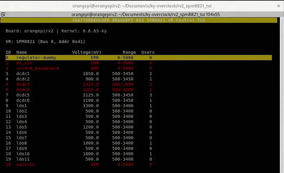
Now, we need to double check if the voltage we’re setting is actually what we’re setting. There are two ways to do that:
- We can use our telemetry tool, and
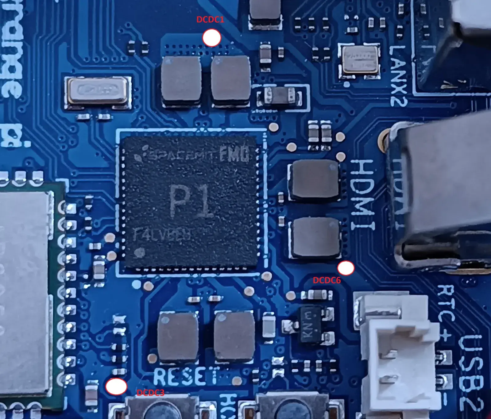
- We can probe the hardware directly
For option 2, I started mapping the voltage readout points on the PCB. Here’s a preliminary overview.
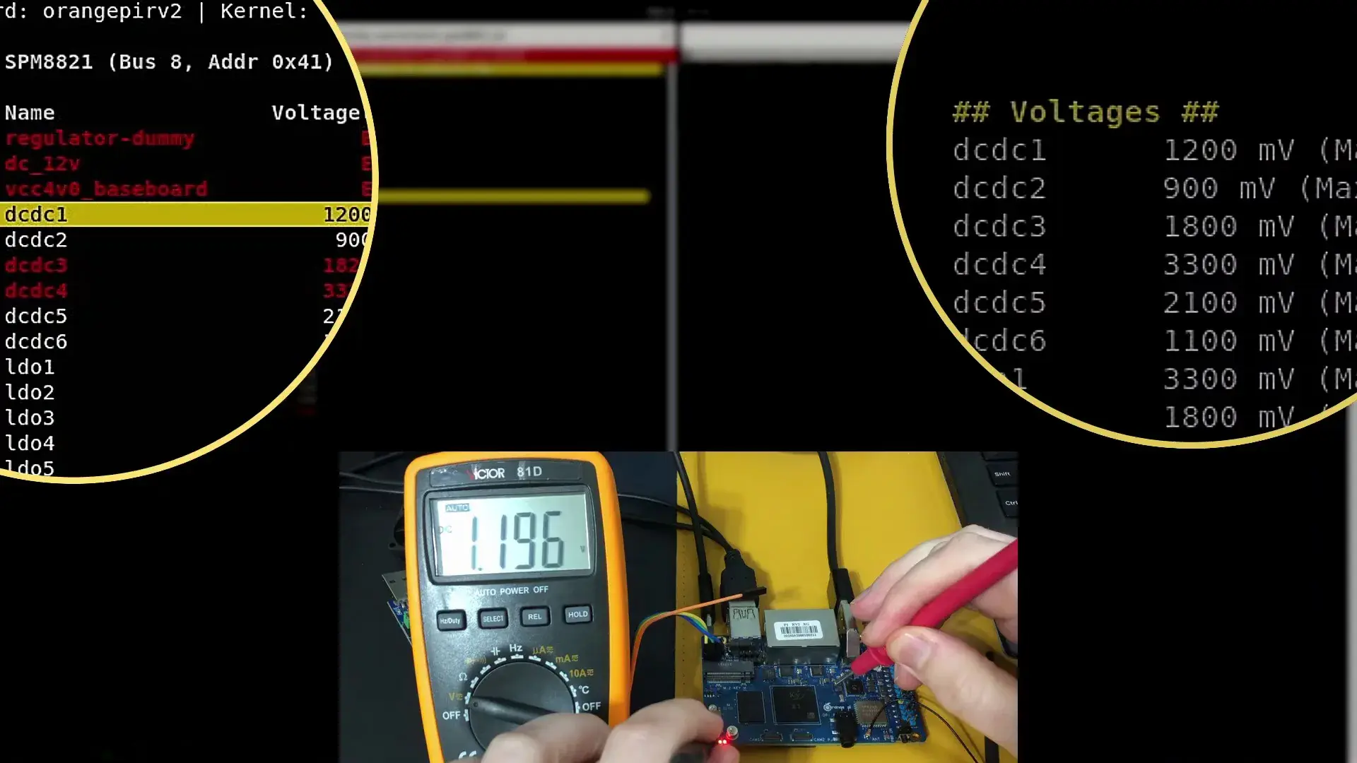
As an example, let’s try setting DCDC1 (for CPU cores) to 1.2V. It all seems to work as intended.
OrangePi RV2 Frequency Tuning
Last but not least, we want to adjust the operating frequency to achieve higher performance. Configuring the frequency is not a trivial activity as it involves several layers from kernel to hardware to work together.
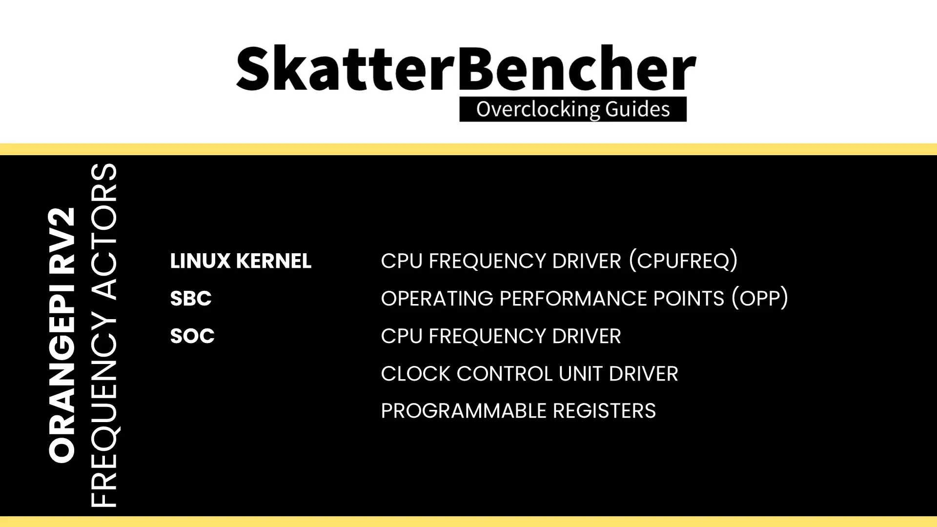
Let’s have a look at the CPU frequency first. We can distinguish the following actors:
- Linux Kernel: CPU Frequency Driver (CPUFreq)
- SBC: Operating Performance Points (OPP)
- SOC:
- CPU Frequency Driver
- SoC Clock Control Unit Driver
- SoC programmable registers
The CPUFreq subsystem is the Linux kernel’s framework for dynamic CPU frequency scaling. It provides standard interfaces and governors that decide how and when to adjust CPU frequencies. SoC-specific CPUFreq drivers translate these decisions into hardware-specific actions.
Supported frequency and voltage pairs, better known as Operating Performance Points (OPPs), are typically defined in the board-specific device tree. Together with the SoC-specific frequency driver, they determine what the clock control unit driver programs the SoC registers.
Linux Kernel CPUFreq Driver
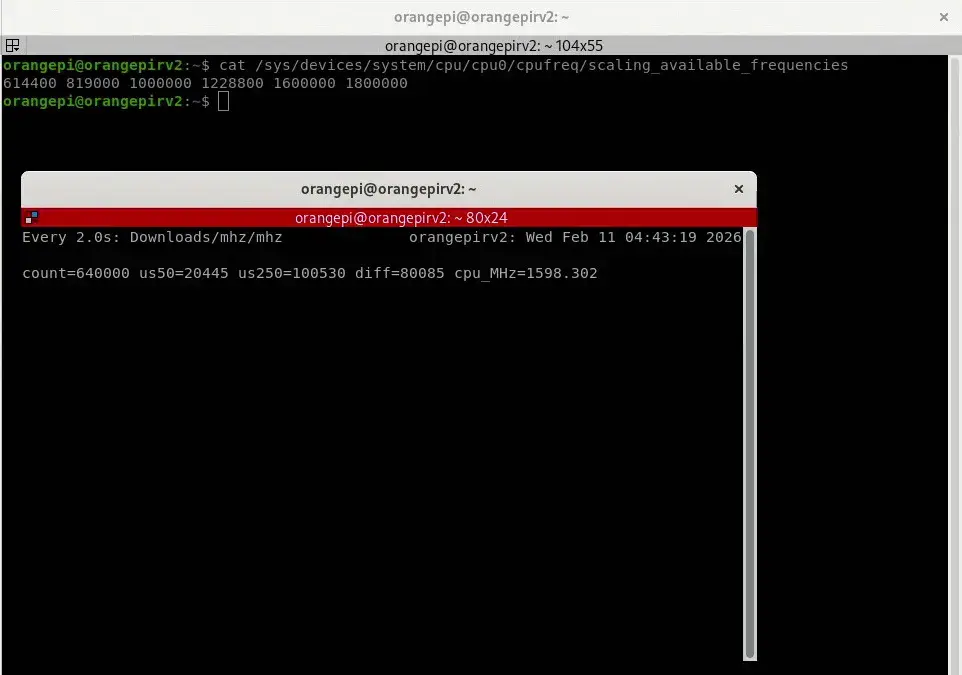
The first place to check is usually the CPU frequency driver. On the RV2, we can access the available frequencies with this command:
cat /sys/devices/system/cpu/cpu0/cpufreq/scaling_available_frequenciesWe can adjust the frequency with scaling_max_freq and scaling_setspeed. For example, we can set the maximum frequency to 1000 MHz with the following command:
echo 1000000 | sudo tee /sys/devices/system/cpu/cpu0/cpufreq/scaling_max_freqThis will work with any performance governor. But if we want to define a specific clock frequency, we can switch the governor to userspace and define the frequency directly:
echo userspace | sudo tee /sys/devices/system/cpu/cpu0/cpufreq/scaling_governor
echo 1000000 | sudo tee /sys/devices/system/cpu/cpu0/cpufreq/scaling_setspeed
Now, you can only pick a frequency from the available frequencies. This list is determined by the CPU cluster’s OPPs or Operating Performance Points. These points are basically V/F points which are defined in the board-specific device tree binary.
OrangePi RV2 OPPs
We can find the OPPs in the device tree that’s loaded at boot. We can find the specific device tree binary by first checking /boot/boot.cmd:
load ${devtype} ${devnum} ${fdt_addr_r} ${prefix}dtb/${fdtfile}Now, we can check the /boot/orangepiEnv.txt configuration file:
fdtfile=ky/x1_orangepi-rv2.dtbNow we can convert the binary dtb into a human-readable dts file.
dtc -I dtb -O dts -o x1_orangepi-rv2.dts x1_orangepi-rv2.dtbNow we can look through the device tree and find the operating points. They’re defined in opp_table0, opp_table_1, and opp_table2.
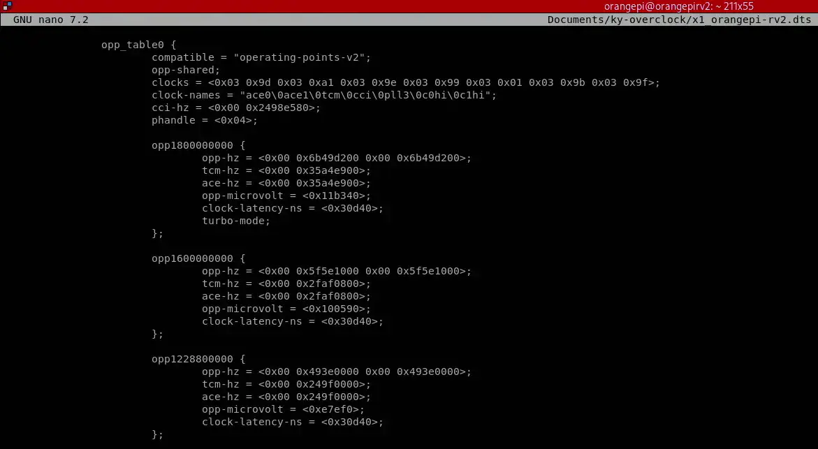
When I first looked through the dts, I was very excited because it seemed there was an easy 1800 MHz OPP we could unlock by removing the turbo-mode requirement. To try that, you can simply remove that one line for each opp_table and reconvert the modified dts file into a dtb file.
dtc -I dts -O dtb -o x1_orangepi-rv2_mod.dtb x1_orangepi-rv2.dtbThen place the modified dtb file into the dtb folder and edit the orangepiEnv.txt configuration file. Once you reboot, it should automatically boot to 1800 MHz. However, that wasn’t the case, even though the 1800 MHz frequency point was exposed to the CPUFreq driver.
To understand why, we need to look at the next layer of CPU frequency configuration: the hardware-specific CPUFreq driver.
Ky X1 CPUFreq Driver
The Ky X1 SoC has its own CPUFreq driver which is compiled into the kernel and then used by the Linux kernel CPUFreq driver. Fortunately, we can find the source code for the kernel in the OrangePI GitHub repository.

Reading through this file we can quickly figure out what’s preventing us from boosting to 1800 MHz: there’s a defined K1 max frequency.
#define K1_MAX_FREQ_LIMITATION (1600000)This limitation is called in the spacmeit_cpufreq_veritfy (lol, typo) function where the driver checks which SoC is used and then limits to 1800 and 1600 MHz accordingly.
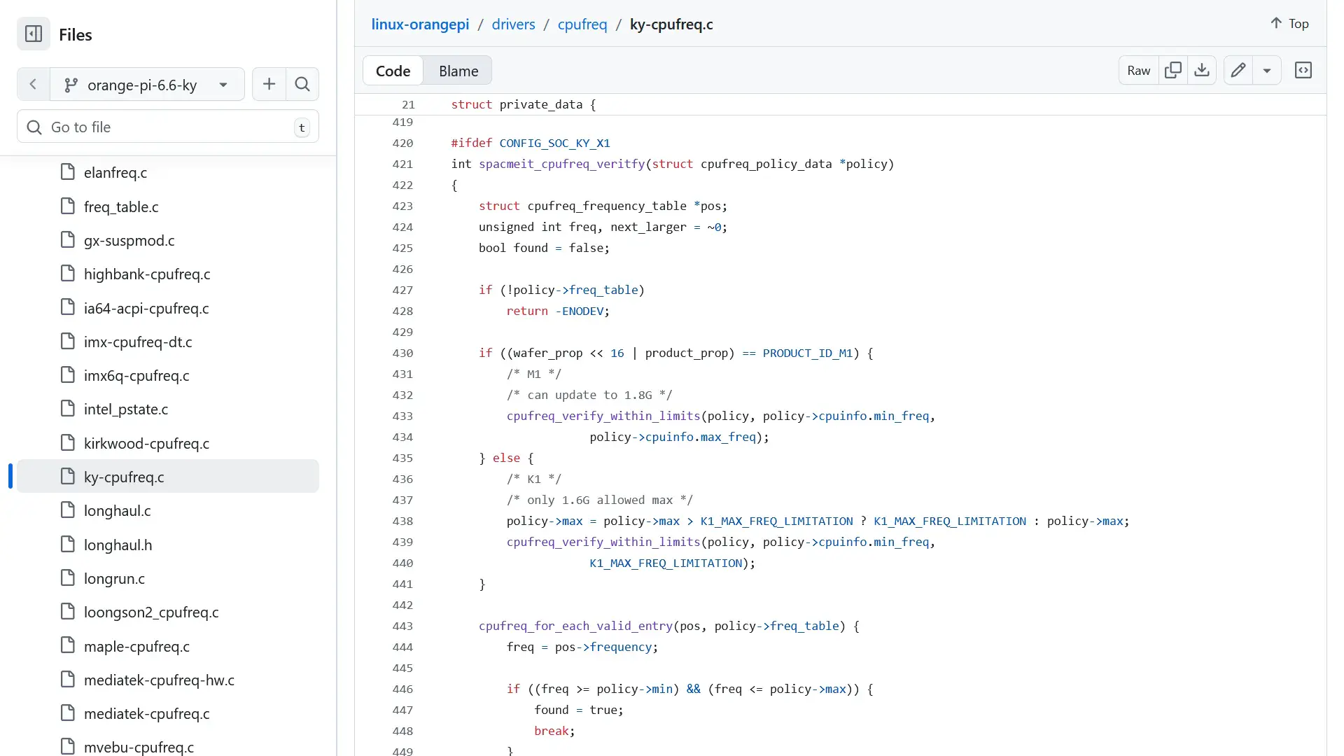
This is easily patchable. We can simply redefine the K1_MAX_FREQ_LIMITATION to any value higher or equal to 1800 MHz, then recompile the Linux kernel, and it should boost.
That’s exactly what I did and it turned out we were correct: the Ky X1 now boosts to 1800 MHz. We can validate the effective clock by running the mhz tool which I used in the OrangePi 5 Max guide as well.
Unfortunately the 1800 MHz setting isn’t too stable for now as it fails to pass 7-Zip even with 1.25V.
Of course, the next question is how to achieve higher frequencies. Onto the next layer!
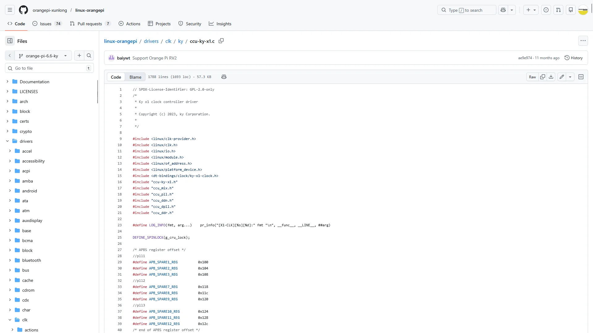
Ky X1 CCU Driver
While the SoC-specific CPUFreq driver handles the policy related requests, it’s the Clock Control Unit (CCU) driver that manages the actual clock changes in the SoC registers. This file is also available in the kernel source code.
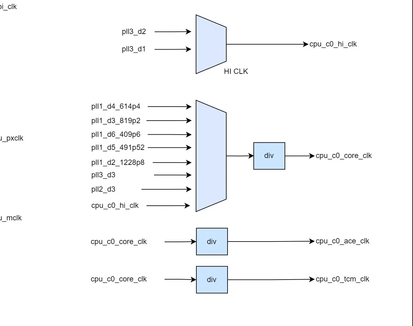
But before we get to that, first check out the clock topology provided by SpaceMit. This helps us understand how the clock tree works. Double thumbs up to SpaceMit for providing such detailed information!

What we find is that PLL3_D1 and PLL3_D2 serve as main reference clock to both CPU clusters. D1 and D2 stand for divided by 1 and divided by 2. These connect to the “High Clock” which is one of the available PLL input clocks for each of the two clusters. The core clock then serves as an input clock for the cluster0 and cluster1 ace, tcm, aclcks, and pclks. PLL3_D1 and _D2 are two of the eight available PLL3 sub-clocks while PLL3 itself is derived from the 24 MHz clock crystal. By default, PLL3 is 3.2 GHz but it can also run at different frequencies depending on the SoC configuration.
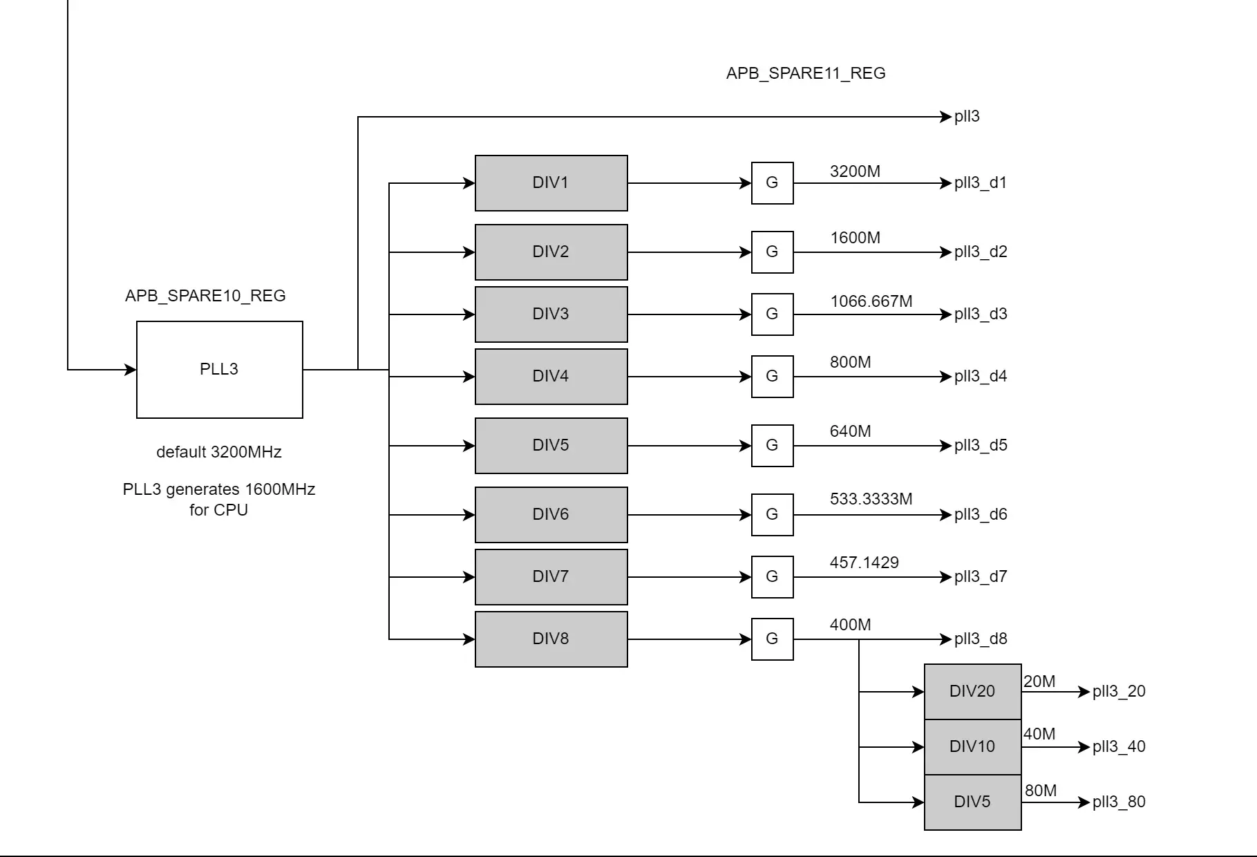
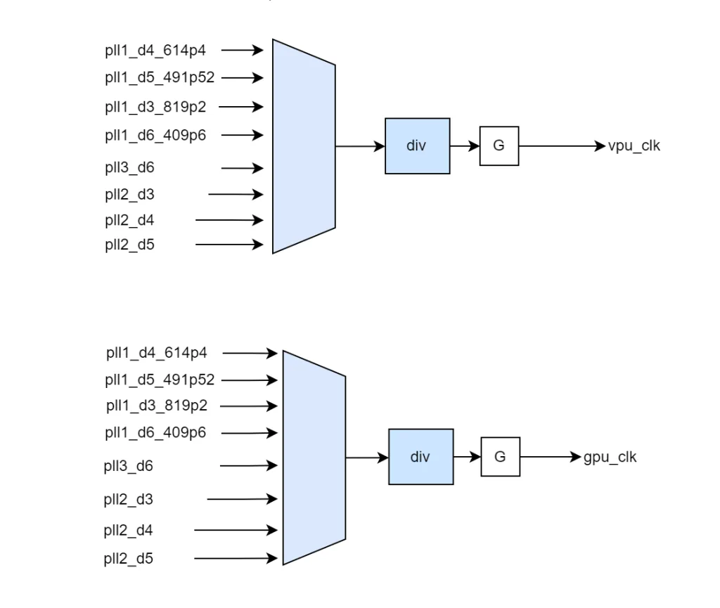
Also important is that there’s other devices also using the PLL3 reference clock, including rcan0 and can0 as well as the GPU and VPU.
To get back to the CPU frequency: when the Linux kernel CPU frequency driver wants to change the frequency, it first negotiates with the SoC-specific Ky X1 frequency driver what’s the appropriate frequency (limited by max frequency and OPPs), then relies on the CCU driver to actually program the SoC registers.
In our case, if we want to increase the frequency beyond 1800 MHz, we not only need an OPP higher than 1800 MHz but we also need to have the SoC know how to program PLL3 to support the higher frequency.
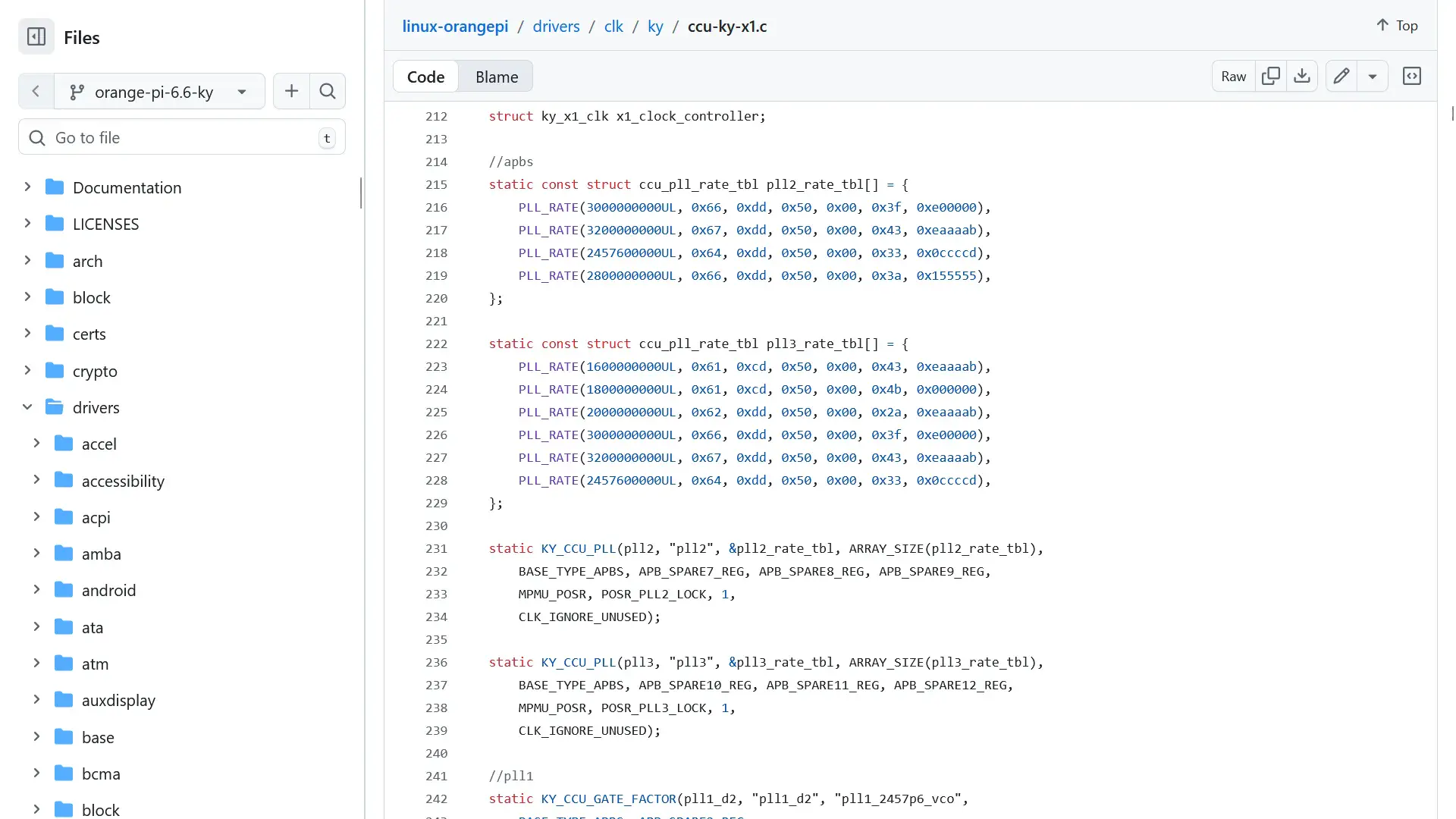
In the CCU driver we can find a handy table for the PLL3 configuration with the configuration for 1600 MHz, 1800MHz, 2000 MHz, 3000 MHz, 3200 MHz, and 2457.6 MHz. In theory this should allow us to program at least 4 frequencies higher than 1800 MHz.
So, I tried adding an OPP for 2000 MHz but unfortunately I got a kernel panic before loading the operating system. That probably means it’s trying to apply the frequency but something is unstable.
Ky X1 SoC Registers
What would be even more useful is if we’d be able to overwrite the clock frequency at runtime without having to reboot and read from the OPP table. That’s how we got the high frequency on the RK3588 on LN2 in SkatterBencher #91.
This turns out to be more complicated than expected too. The positive news is that, again, SpaceMit is providing a lot of register documentation on their developer website. In fact, it’s much more information that we’d get from established overclocking players in the X86 space!
I put together a preliminary tool to read and write register values at runtime to help with debugging. It includes a range of relevant registers for CPU, GPU, VPU, and others. I think most of it is correct but the tool is still alpha version.
GitHub link: https://github.com/SkatterBencher/orangepi-rv2-tools/tree/main/ky-x1-soc-tui.
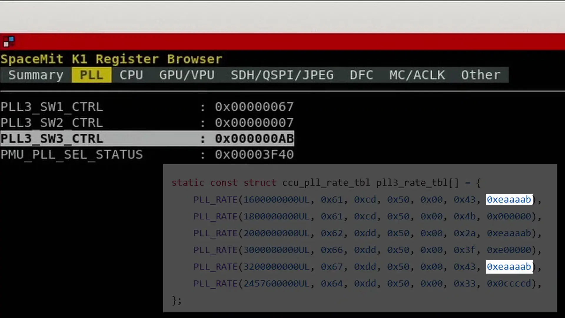
SpaceMit is opening up a lot of configuration options, but not all the important registers for our overclocking adventure are accessible. Specifically, the registers related to PLL3 programming are not only read-only but also we cannot read out the entire value. For example, according to the PLL3 table the SW3 value for 1600 MHz or 3200 MHz should be 0xeaaaab but we only see 0xab.
OrangePi RV2 Conclusion
That’s it as far as my RV2 tuning adventure goes. As you can see, we’re able to get some performance tuning going with the performance governors and unlocking the maximum frequency, and I think we’re able to set higher values with the PLL3 information, but we’re far from ready to put together a comprehensive overclocking guide.
I’ll continue to work on this project for the coming weeks and months and if I make any kind of progress you’ll see it pop up in the form of a SkatterBencher guide and 5 Minute Overclock.
Anyway, that’s it for today.
I want to thank my Patreon supporters and YouTube members for supporting my work. If you have any questions or comments, please drop them in the comment section below.
See you next time!