SkatterBencher #91: Rockchip RK3588 Extreme Overclock to 3454 MHz
We overclock the Rockchip RK3588 of the Orange Pi 5 Max to 3454 MHz with extreme liquid nitrogen cooling and our home-brew overclocking tools.
Rockchip RK3588 Extreme: Introduction
Hi, and welcome back!
As I already hinted at in my Orange Pi 5 SkatterBencher guide, I took the SBC for a spin with liquid nitrogen aiming to achieve the highest possible frequency. As expected, operating a small SBC with such extreme cooling techniques wasn’t without its challenges. However, we did achieve 3454 mhz as well as some interesting Geekbench and High Performance Linpack benchmark results.
In this blog post, I cover three overclocking strategies
- SkatterBencher #89, OC Strategy #3, at -30 degrees Celsius
- Maximum PVTPLL overvolt at -100 degrees Celsius
- Maximum Frequency
But, before we jump into the nitrogen, let’s start where we left off in SkatterBencher #89.
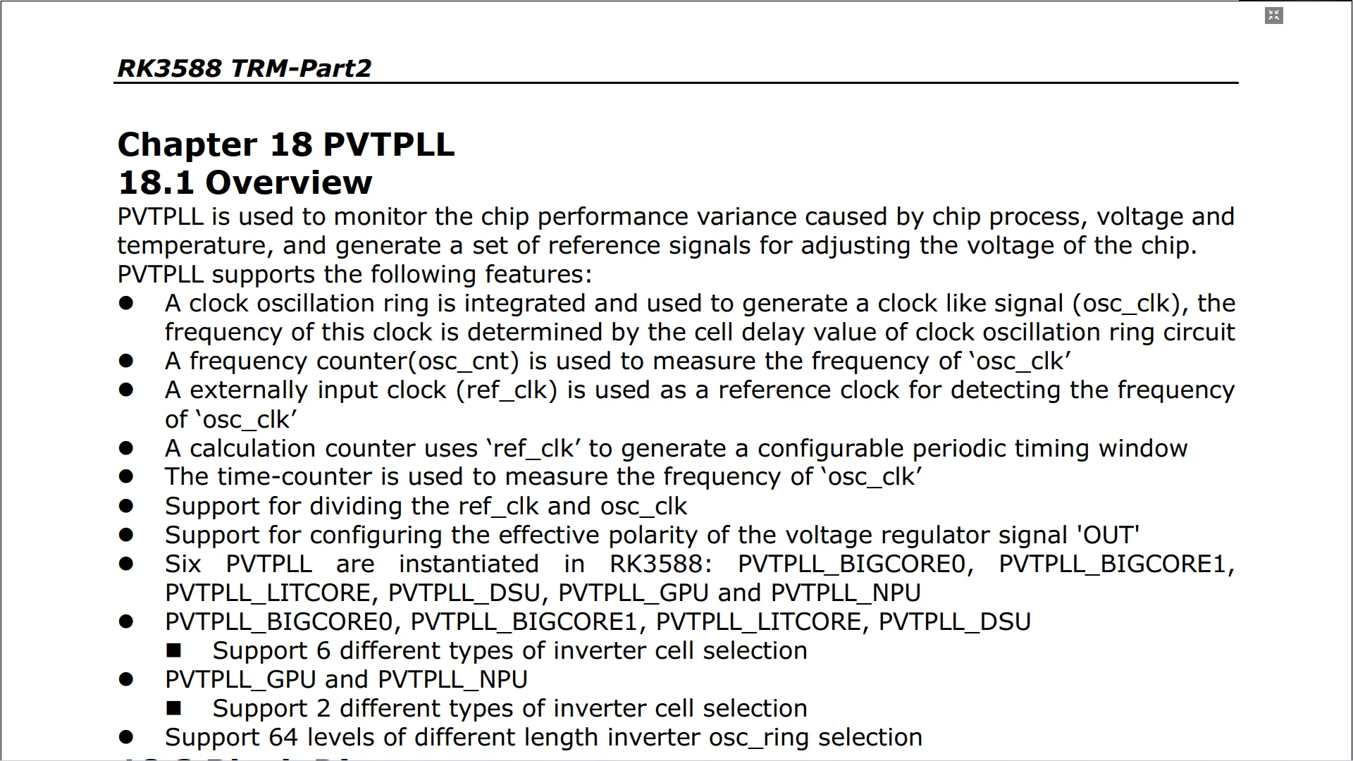
Rockchip RK3588: PVTPLL Temperature Scaling
In SkatterBencher #89 I overclocked the Orange Pi 5 Max to 2650 MHz by overvolting the adaptive PVTPLL clocking circuit. I also built my own tool to measure and configure the operating frequency but with limited success. Turns out the PVTPLL is pretty good at squeezing the highest frequency out of the Orange Pi.
As a reminder, PVT stands for Process-Voltage-Temperature. So PVTPLL is an adaptive clocking technology that should adapt the operating frequency to the silicon quality (Process), operating voltage (Voltage), and operating Temperature (Temperature).
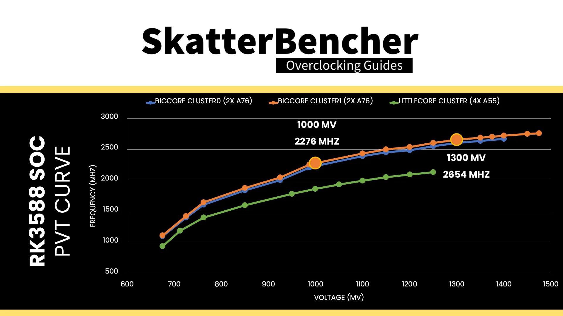
I already illustrated the adaptive frequency behavior in my SkatterBencher guide. For example, BigCore Cluster1 runs at 2276 MHz at 1.0v and 2654 MHz at 1.3v. Now, let’s look at the temperature impact on the PVTPLL frequency.
RK3588 PVTPLL Temperature Scaling at Default Voltage
I plotted the operating frequency of the A55 cluster and both A76 clusters as function of a decreasing temperature starting at 80 degrees Celsius and ending at -196 degrees Celsius. This is with the default voltages of 950 mV for the A55 cores and 1V for the A76 cores.
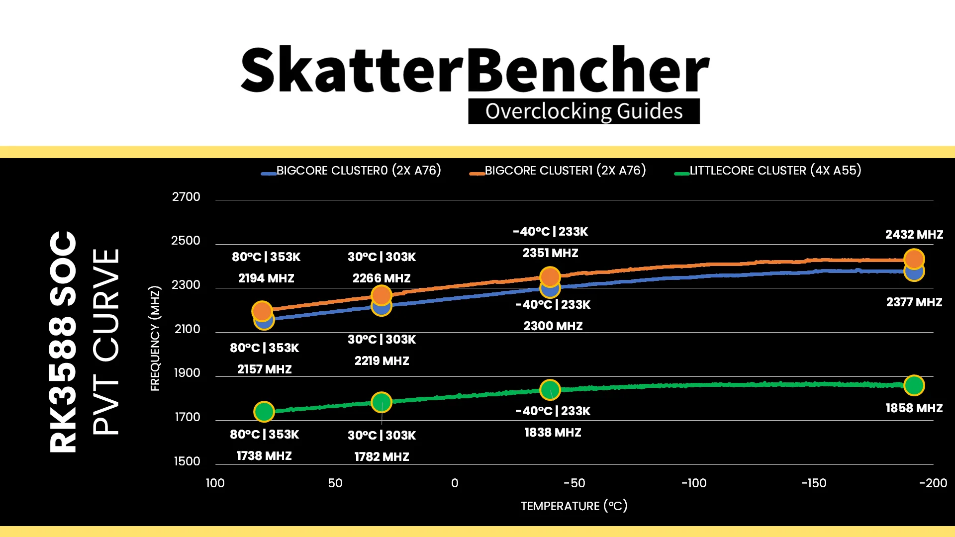
We find that at 80 degrees Celsius (353 K) the operating frequency for the A55, A76 Cluster0, and A76 Cluster1 is 1738, 2156, and 2194 MHz respectively. The frequency gradually increases as the temperature drops. For example, at 30 degrees Celsius (303K) the operating frequency is 1782, 2219, and 2267 MHz respectively. That’s a frequency increase of about 3% for a 14% decrease in temperature (using the Kelvin scale).
At -40 degrees Celsius (233 K), the operating frequency is 1838, 2300, and 2351 MHz respectively. That’s an increase of 5.83 to 6.99%. Note that we’re still not hitting the advertised frequency of 2.4 GHz for the A76 cores!
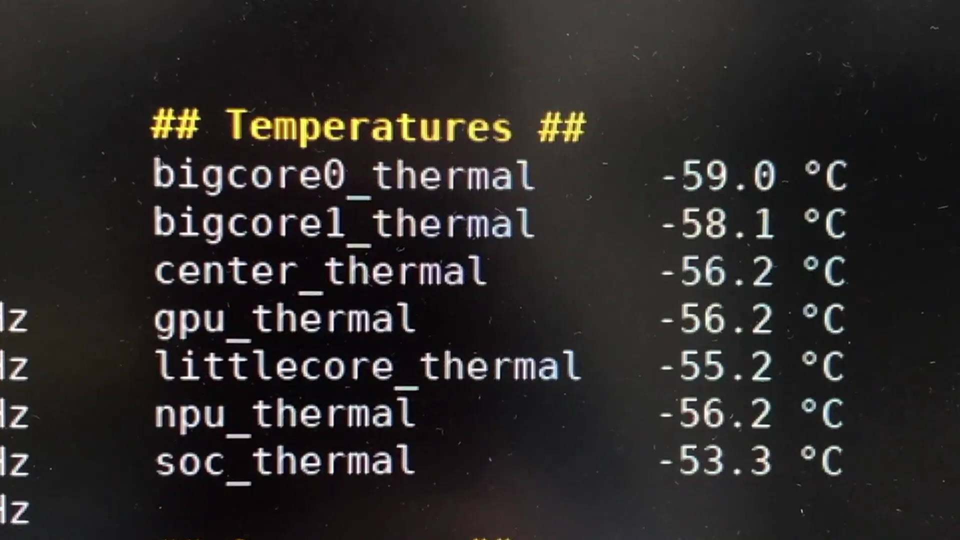
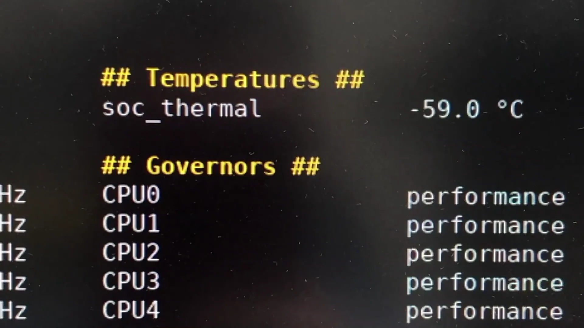
Then, at -60 degrees Celsius, something strange happens. All of a sudden, our temperature telemetry disappears and my telemetry tool can no longer log the operating temperature. It’s of course not that unusual that sensors stop working at that low of a temperature, though it has to be said that the Raspberry Pi 5 could display temperatures down to -90 degrees Celsius.
Surprisingly, however, the Orange Pi 5 Max is capable of operating at “full pot” conditions, meaning the liquid nitrogen reaches a steady state and the temperature would be about -190 degrees Celsius (83 K). At that temperature, we reach a maximum frequency of 1860 MHz for the A55 cores, 2377 MHz for A76 Cluster0, and 2432 MHz for A76 Cluster1. Finally, we get the advertised 2.4 GHz though it required an operating temperature of well below -100 degrees Celsius.
In summary, we get about a 10% increase in frequency for a 75% decrease in operating temperature. Not amazing, but it confirms the impact of “T” in PVTPLL.
RK3588 PVTPLL Temperature Scaling at Maximum Voltage
For science, I also tracked the operating frequency for the two A76 clusters with an operating voltage of 1.5V – the maximum supported voltage of the voltage regulator.
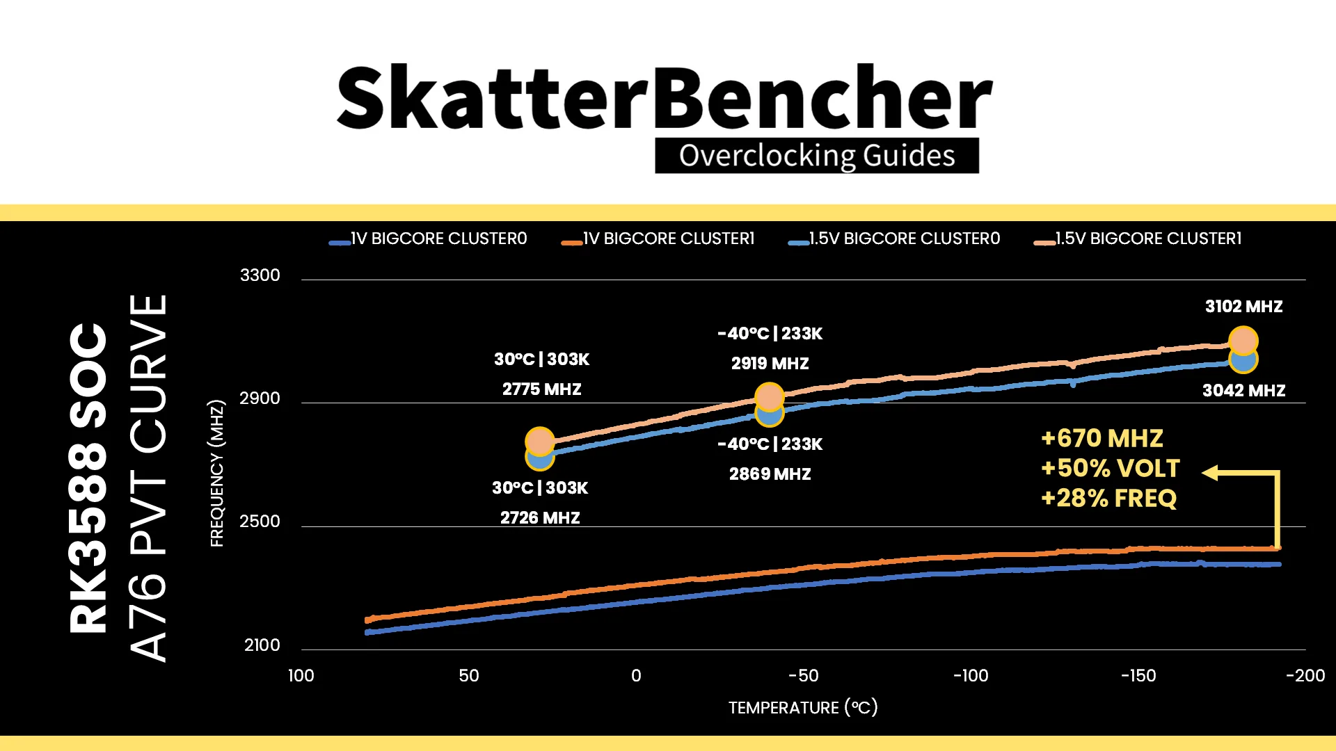
At 30 degrees Celsius (303 K), the frequency is 2726 and 2775 MHz for Cluster0 and Cluster1, respectively. That’s about 500 MHz higher than at the default 1V (2220 & 2267 MHz), so we’re seeing an increase of about 22% in operating frequency with 50% higher voltage.
At -40 degrees Celsius (233 K), the operating frequency is 2869 and 2919 MHz respectively. That’s 560 MHz higher than what we got at the same temperature but with 1V (2300 & 2351 MHz), meaning we now have a 24% increase in frequency with the same 50% increase in operating voltage.
The highest frequency achieved was 3042 MHz for A76 Cluster0 and 3102 MHz for A76 Cluster1. That’s 670 MHz higher than what we got with 1V at the same temperature (2377 & 2432 MHz) – a 28% increase in operating frequency for a 50% increase in operating voltage.
So, it seems higher voltages get more effective at lower temperatures. Good to know!
XOC Strategy #1: Operating Subzero
With the knowledge that lower temperatures yield higher operating frequencies, I decided to first try the same settings from SkatterBencher #89, OC Strategy #3 but with a lower operating temperature.
But how low? Well, that’s a bit complicated.
ARM DynamIQ Shared Unit Fmax
The PVTPLL temperature scaling tests led me to believe I could possibly run the Orange Pi 5 Max under “full pot” conditions. Unfortunately, that’s not quite true because of a particular hardware design decision related to the DSU.
DSU stands for “DynamIQ Shared Unit” and it’s essentially ARM’s version of Intel’s Uncore. The DSU contains not only the L3 cache but also the memory controller, and effectively acts as the central hub connecting the CPU cores with the rest of the SoC IP blocks.
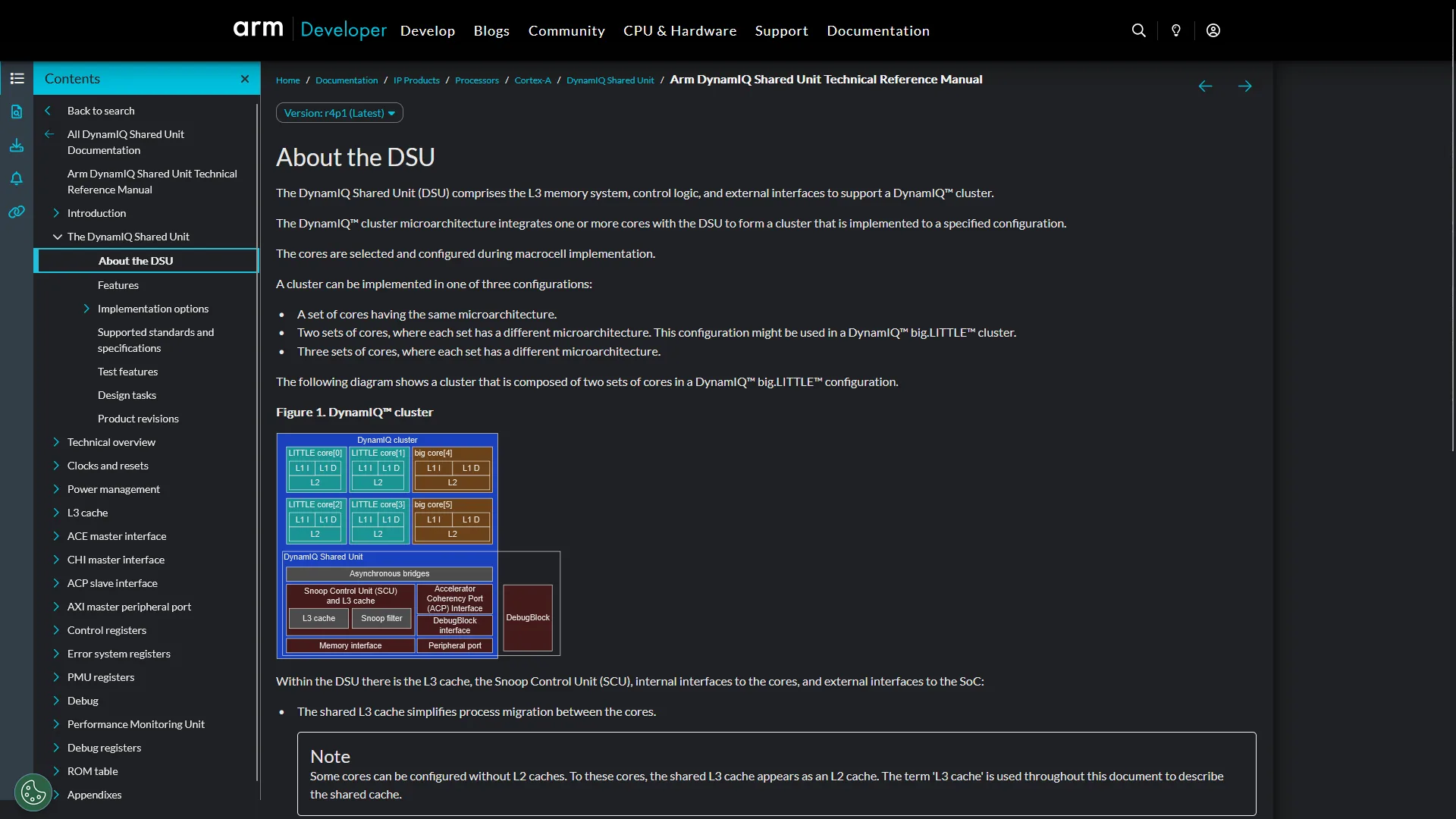
On the Rockchip RK3588, the DSU has its own PVTPLL clocking domain and can be clocked independently. However, on the Orange Pi 5 Max, the DSU voltage is provided by the same vdd_cpu_lit_s0 voltage rail as the Cortex-A55 quad-core cluster. In PVTPLL mode, that means the DSU frequency goes up when we increase the voltage for the A55 cores.
Furthermore, the PVTPLL configuration of the DSU and A55 are the same. That means they run the same frequency at the same voltage. In SkatterBencher #89, I didn’t pay too much attention to this detail, but perhaps I should’ve because it turns out the DSU is a key limiting factor when pushing the RK3588 to its limits.
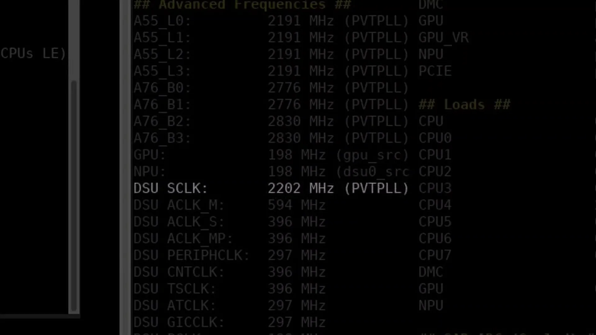
The maximum stable operating frequency of the DSU is about 2200 MHz – no matter how heavy the workload. We kind of saw this problem at ambient as we couldn’t increase the vdd_cpu_lit_s0 voltage above 1.25V without sacrificing stability. At 1.25V, the DSU runs at about 2.15 GHz and increasing the voltage by 50 mV would add about 40 MHz.
Now, the issue for our extreme overclocking session is with the T in PVTPLL because operating at a lower temperature also increases the operating frequency.
For example, the A55 cluster runs at 2250 MHz at -40 degrees Celsius and 1.25V. That frequency is not possible for the DSU.
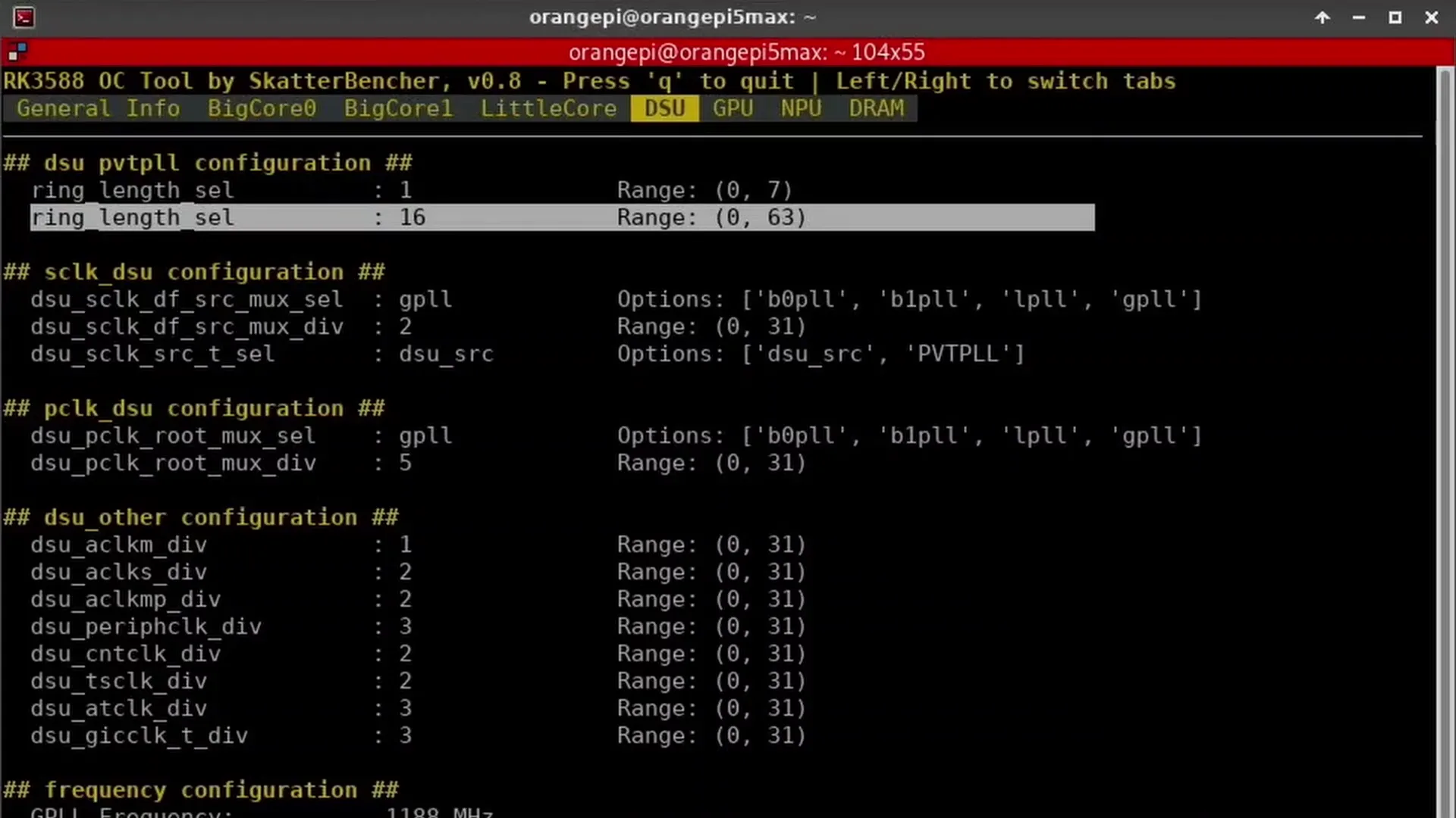
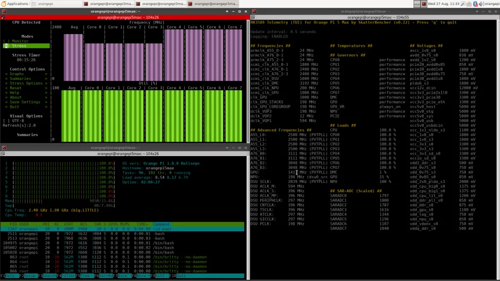
So, the only workaround is to slightly adjust the DSU operating frequency. We can do this at runtime using my RK3588 OC Tool by simply adjusting the DSU PVTPLL ring length from 15 to 16. That reduces the DSU operating frequency to 2170 MHz at 1.25V and allows us to run the SoC stably at about -20 to -30 degrees Celsius.
Note that this configuration isn’t stored in any kind of BIOS, so if the board is unstable and we need to reboot, we must heat up to about 0 degrees Celsius. Otherwise, the DSU clock is too high. I’m not sure if there’s any way to store different ring length values in the RK3588 SoC so we’d be able to more comfortably boot at subzero temperatures.
Benchmark Results
We rerun the benchmarks and check the performance increase compared to the default operation.
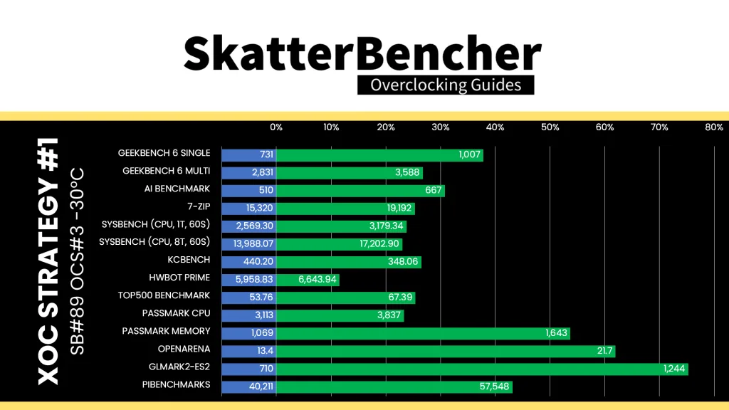
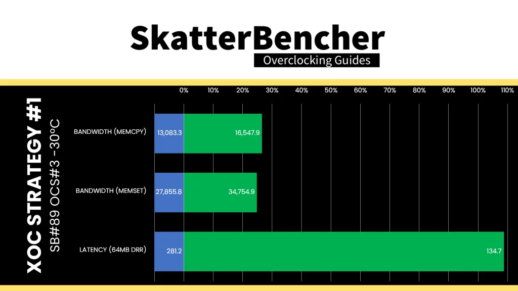
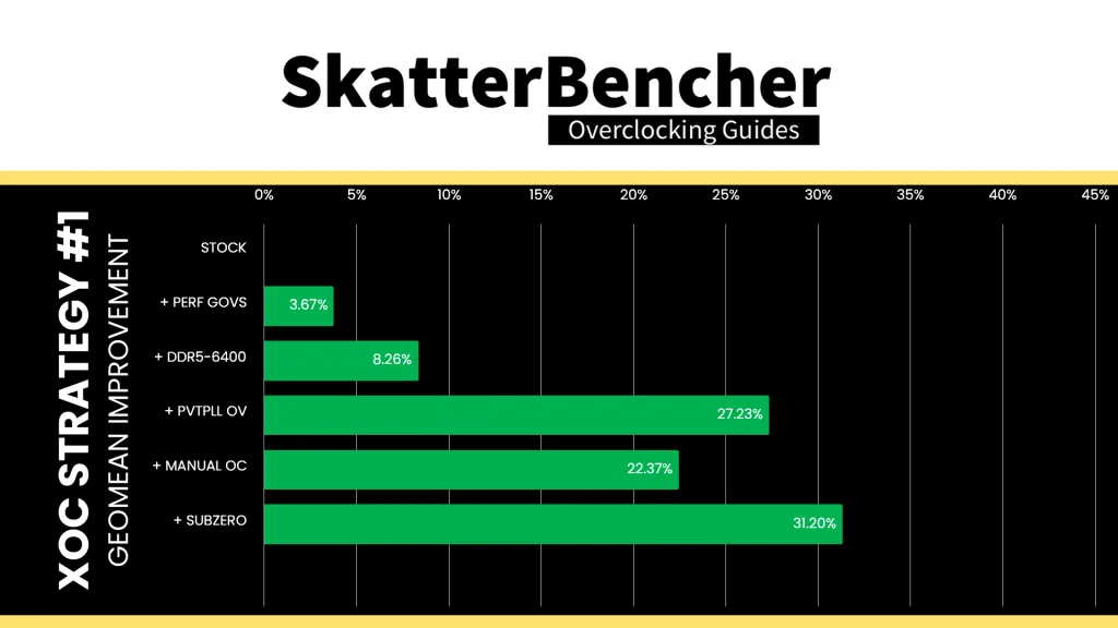
Reducing the operating temperature pushes the adaptive PVTPLL frequency up slightly. This slight frequency increase translates in an equally slight improvement in performance across the board. The Geomean performance improvement over stock is now +31.20%, and we get a maximum benchmark performance improvement of +75.21% in GLMark2-ES2.
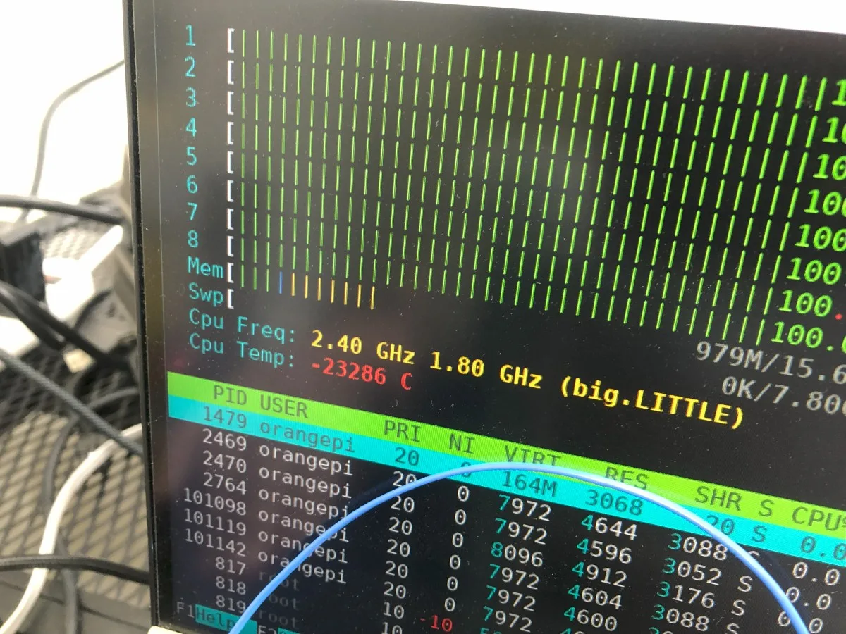
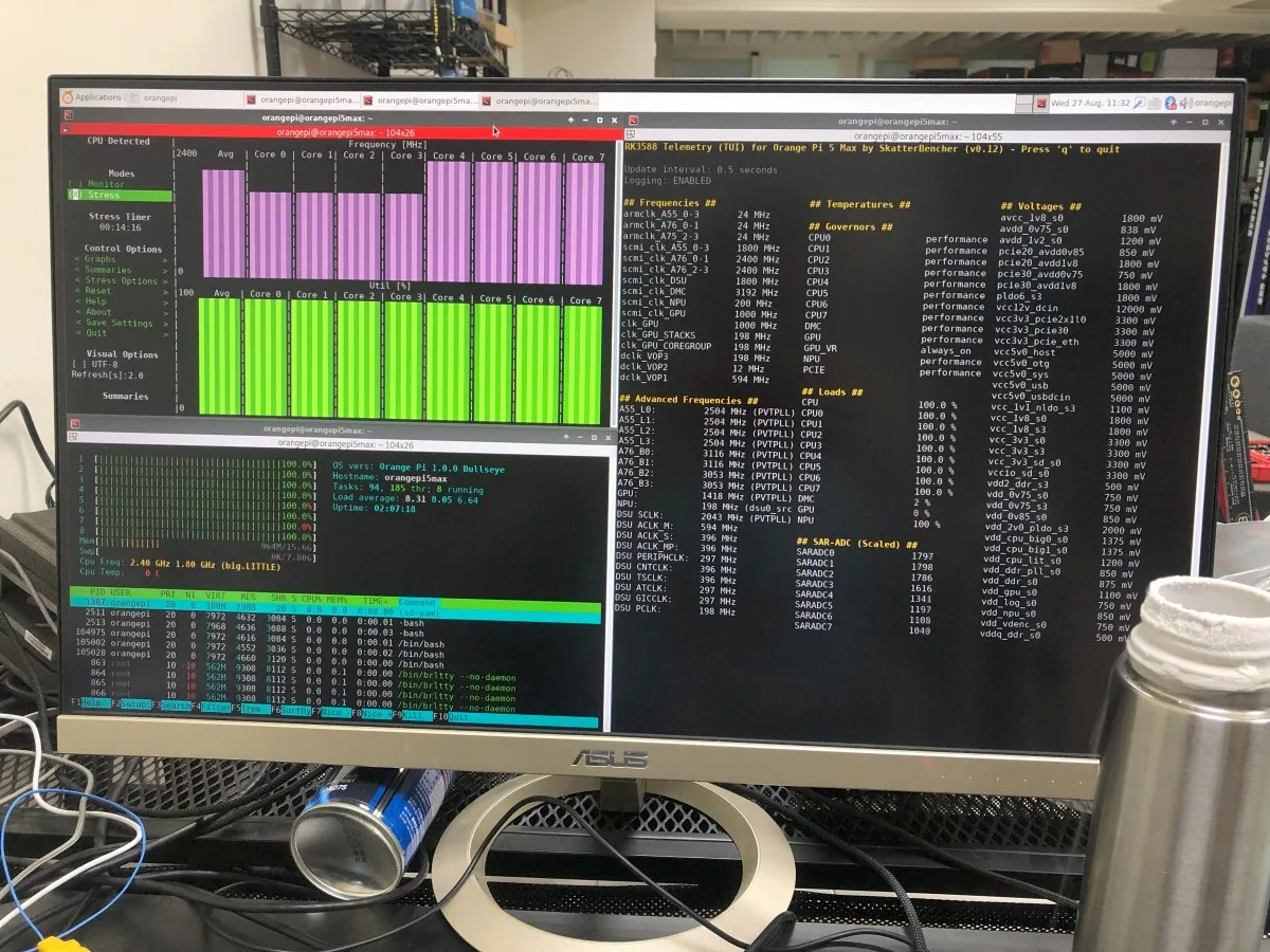
When running the S-TUI Stability Test, the average A55 Cluster clock is 2219 MHz with 1.25 volts, the average A76 Cluster0 clock is 2709 MHz with 1.300 volts, and the average A76 Cluster1 clock is 2761 MHz with 1.300 volts. The average SoC temperature is -28.2 degrees Celsius. The approximate wall power consumption is 21 watts.
XOC Strategy #2: Maximum Overvolt
The next step in our extreme overclocking adventure is to push for higher voltages and lower temperatures. From our PVTPLL testing, we know that increasing the voltage has a much bigger impact on the PVTPLL frequency than decreasing the operating temperature.
However, again, this was not without its issues.
Orange Pi 5 Max Voltage Topology
We covered the Orange Pi 5 Max voltage topology in depth in the Orange Pi 5 Max overclocking guide, but let’s quickly recap for those who missed that guide.
The Orange Pi 5 Max voltage topology consists of 1x RK806 PMIC and 2x RK860 step-down DC/DC voltage regulators.
- The RK806 PMIC takes care of the vast majority of the voltage regulation, including vdd_gpu (DCDC_1) for the GPU and vdd_cpu_lit (DCDC_2) for the A55 cluster and DSU.
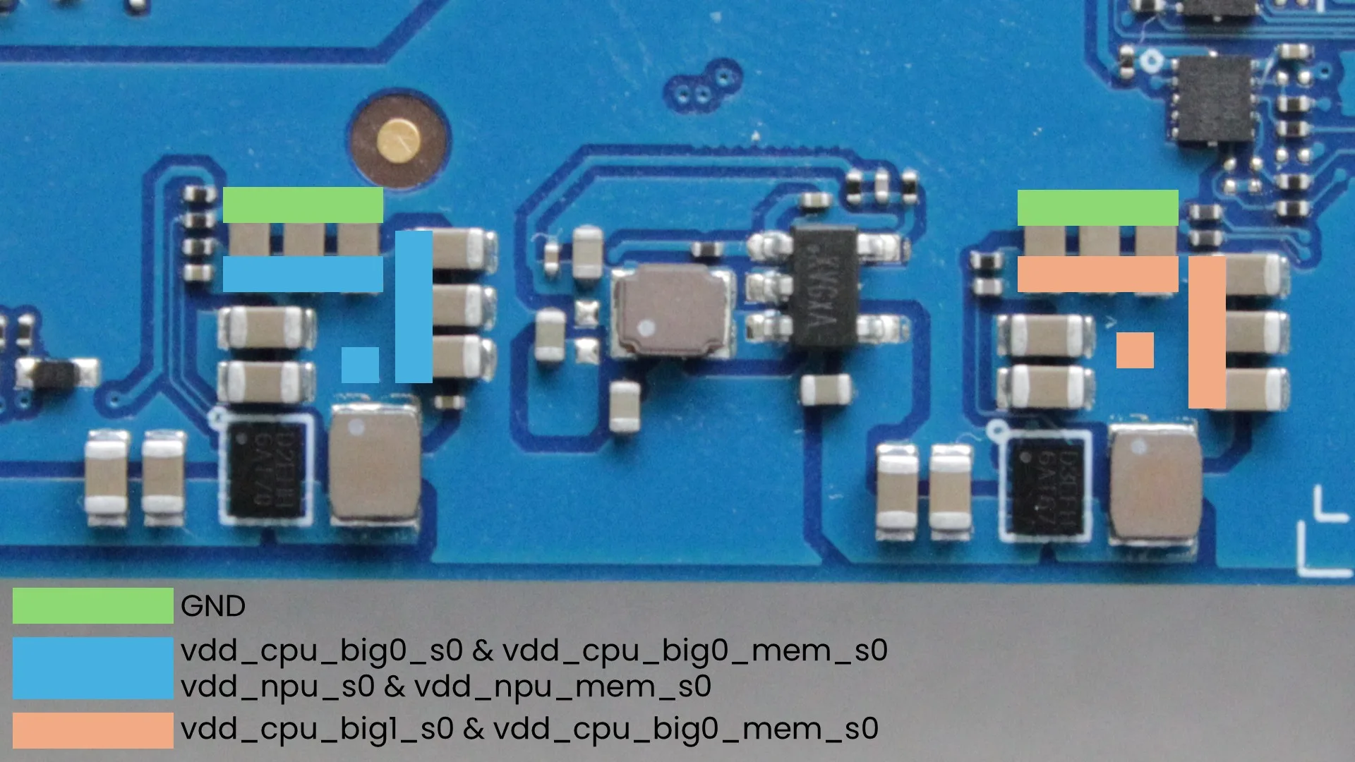
- One RK860 VR provides the voltage for A76 Cluster0 (vdd_cpu_big0) and the NPU (vdd_npu), whereas the other provides the voltage only for A76 Cluster1 (vdd_cpu_big1).
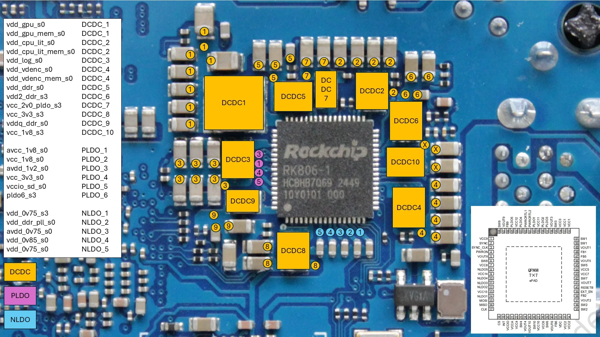
It’s relatively easy to unlock the voltage range for each of these voltage rails as I demonstrated in SkatterBencher #89. However, that doesn’t mean we can easily increase the voltages!
- RK806 DCDC1 vdd_gpu is limited by the GPU capability. I found that the GPU became quite unstable above the 1.1V we used with ambient cooling in SkatterBencher #89, so that’s what I stuck with for this OC Strategy.
- RK806 DCDC2 vdd_cpu_lit is limited by the DSU as it gets unstable around 2.2 GHz. The limit is about 1.25V at ambient, but to run much lower, subzero temperatures I reduced it to 1.20V for this OC strategy
- RK860 vdd_cpu_big0 and vdd_cpu_big1 are limited by heavy workloads causing a board shutdown.
The latter is something we came across when overclocking the Raspberry Pi 5 as well. As I highlighted in SkatterBencher #77, heavy benchmark workloads would shut down the board at around 18W.
For the Orange Pi 5 Max, the shutdown occurs at around 45W from the wall socket. That occurs at 1.45V for Passmark and 1.40V for Jeff Geerling’s High Performance Linpack benchmark. So, for this OC Strategy I stick with 1.375V for both A76 Clusters.
PVTPLL Finetuning
For this OC strategy I also target running at -100 degrees Celsius. So, the PVTPLL adaptive clocking circuit will increase the operating frequency according to the new voltage and temperature situation.
In SkatterBencher #89 I mentioned that the PVTPLL technology seems to be pretty good at extracting the maximum frequency out of each core. But, as it turns out, that’s not quite the case at extremely low temperatures as there’s more frequency headroom.
So, we can use the PVTPLL ring length option in my RK3588 OC Tool to squeeze more frequency out of the PVTPLL clocking domains.
Here’s what the default frequencies look like at the respective voltages and -100 degrees Celsius.
| Domain | Temperature | Voltage | PVTPLL Ring Length | PVTPLL Frequency |
|---|---|---|---|---|
| A55 Cluster | -100°C | 1.20V | 15 14 13 12 | 2257 2338 2432 2518 |
| A76 Cluster0 | -100°C | 1.375V | 10 9 8 | 2894 3013 3144 |
| A76 Cluster1 | -100°C | 1.375V | 10 9 | 2954 3071 |
| DSU | -100°C | 1.20V | 15 18 | 2257 2064 |
| GPU | -100°C | 1.10V | 12 | 1423 |
By fine-tuning the PVTPLL ring length, we can squeeze an extra 260 MHz out of the A55 cores, 250 MHz out of the A76 Cluster0 cores, and 120 MHz out of the A76 Cluster1 cores, while maintaining a high-performance >2GHz frequency for the DSU.
Benchmark Results
We rerun the benchmarks and check the performance increase compared to the default operation.
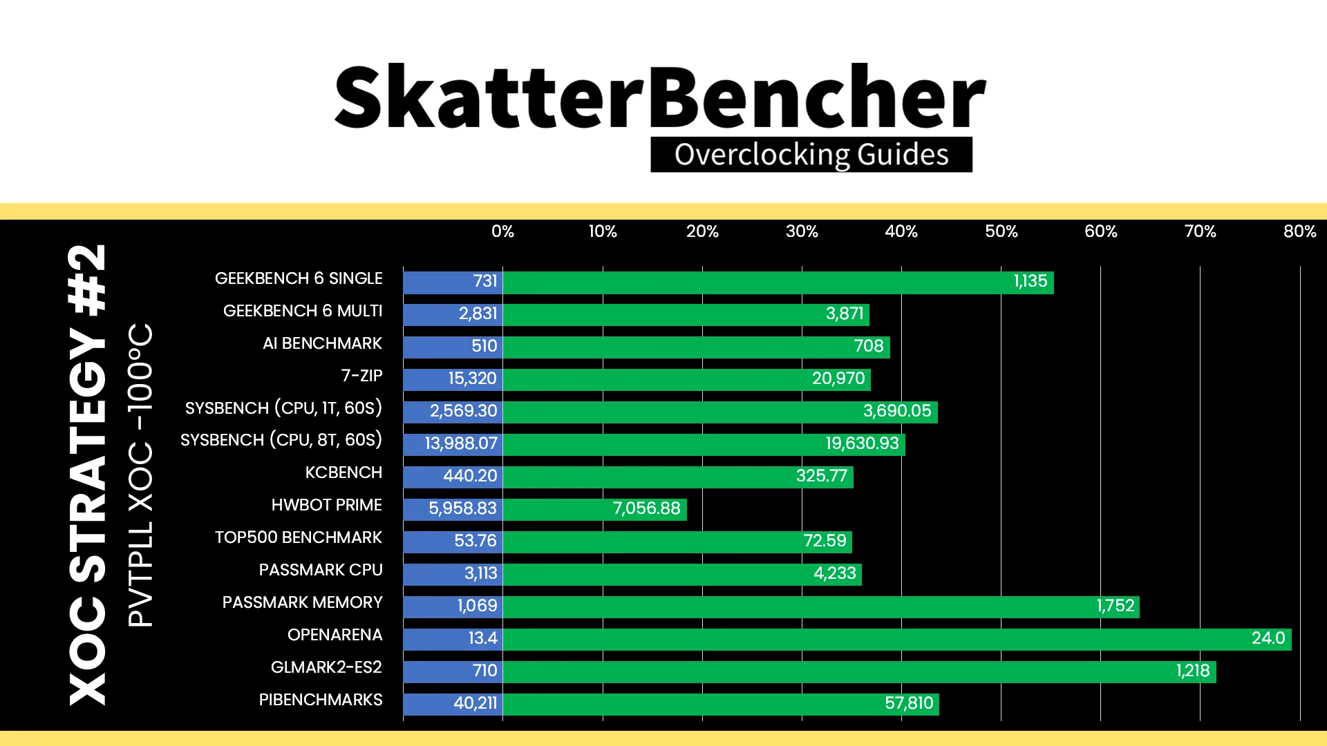
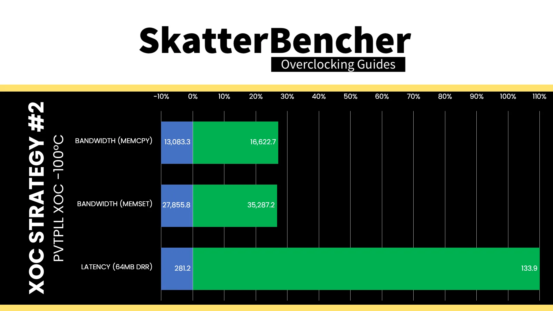
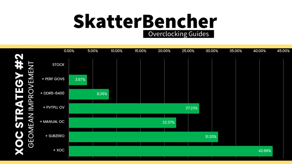
Pushing the RK3588 to its absolute limit shows that there’s still performance left in the tank, though it shows in some places better than in others. It’s pretty cool to see an 8-minute high-performance linpack workload pass at 3 GHz. The Geomean performance improvement over stock is now +42.66%, and we get a maximum benchmark performance improvement of +79.55% in Openarena.
When running the S-TUI Stability Test, the average A55 Cluster clock is 2505 MHz with 1.20 volts, the average A76 Cluster0 clock is 3118 MHz with 1.375 volts, and the average A76 Cluster1 clock is 3054 MHz with 1.375 volts. The average SoC temperature is -100 degrees Celsius. The approximate wall power consumption is 23 watts.

Rockchip RK3588: Maximum Overclock
To wrap up the extreme overclocking adventure, of course we have to push the chip to its absolute limit at the lower possible temperature. So, I tried running the chip at full pot to see if the performance continued to scale.
Maximum Performance
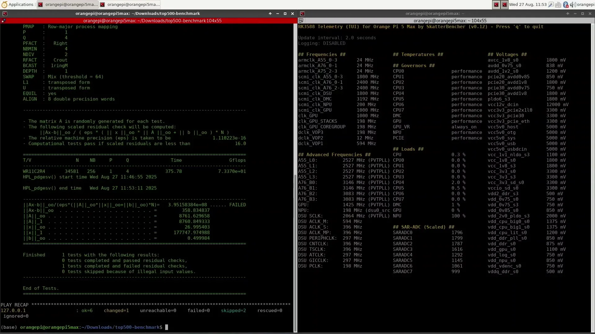
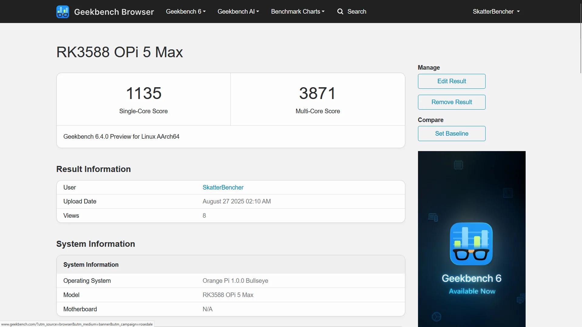
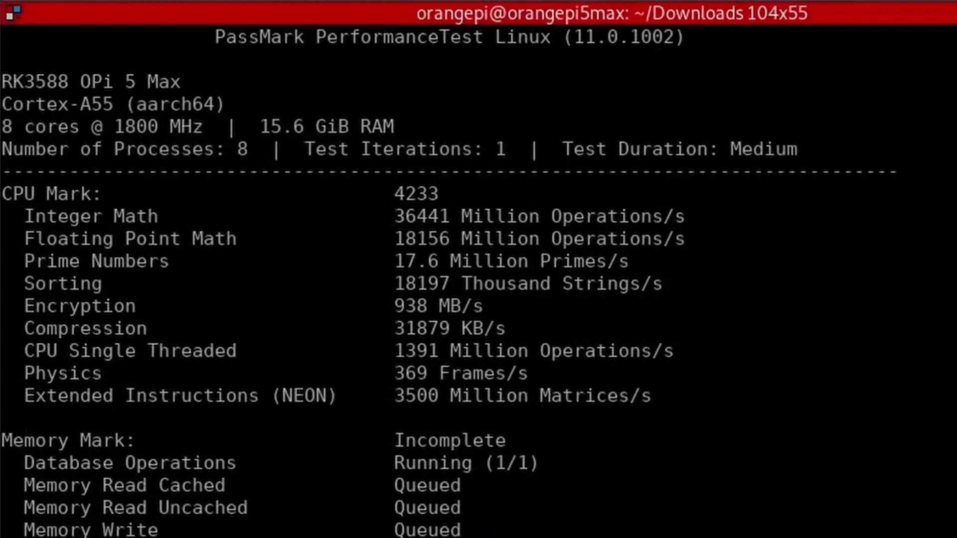
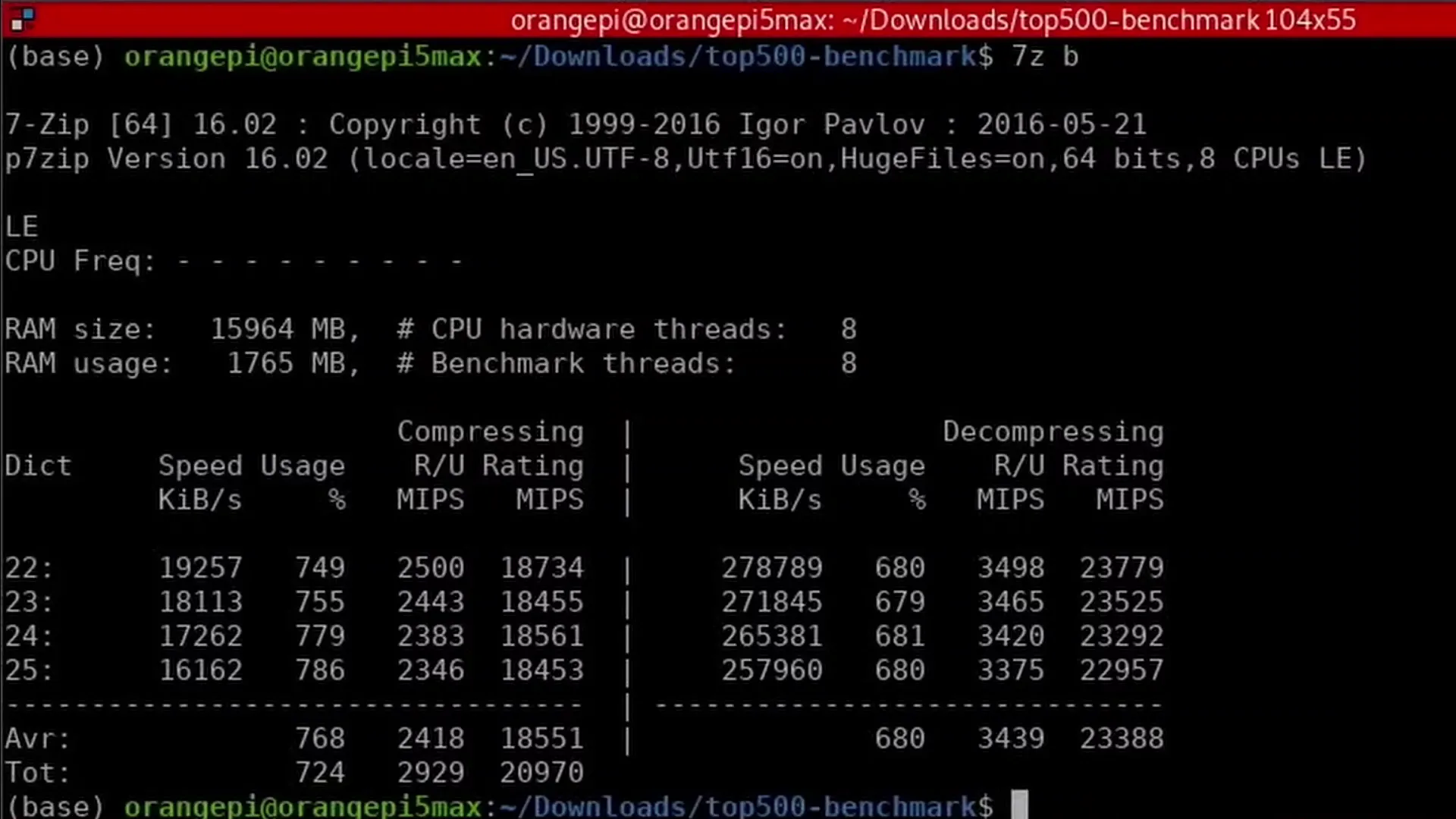
Unfortunately, I was only able to improve the performance in Jeff Geerling’s High Performance Linpack benchmark to 73.37 GFlops. The other benchmarks stay at around the same performance level. So, we get a maximum performance of nearly 3900 points in Geekbench 6, over 4200 points in Passmark, and nearly 21,000 7-Zip mips.
Maximum Frequency
Last but not least, I increased the voltage of the Cortex-A76 cores to squeeze the maximum possible frequency. I increased it to 1494 mV which is right below the 1.5V voltage limit.
Willy Tarreau’s “MHz”
Unfortunately, there’s no CPU-Z database like we have with X86 and Windows platforms to validate the CPU frequency. However, there’s an application called “mhz” by Willy Tareau that we can use to indirectly measure the effective clock frequency – just like we would using CPU-Z on Windows.
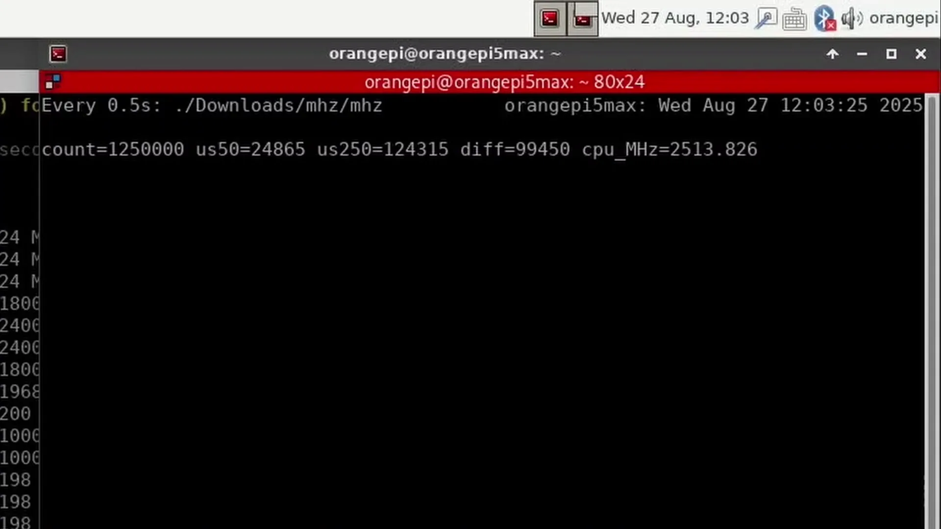
Mhz is a simple but incredibly useful tool that runs long loops of XOR operations that run at a rate of one operation per clock cycle. Using the “taskset” command we can assign the mhz process to the appropriate CPU thread.
Tuning using RK3588 OC Tool
Next is the question of the clocking method. Until now, we’ve relied on PVTPLL tuning to increase operating frequencies. While PVTPLL is useful as an adaptive clocking technology, we don’t have many finetuning tools. So, to achieve the maximum clock frequency, I revert to the UC clock which I briefly discussed in SkatterBencher #89.
The long story short is that I’m programming the A76 cluster-specific reference clock (b0pll and b1pll) to increase the operating frequency. Let’s have a closer look.
The A76 b0 core clock can be controlled from three sources: PVTPLL, Clean, or UC. Usually, we stick with PVTPLL but for the maximum frequency attack we switch to UC.
In UC mode, the core frequency is the bigcore0_mux clock divided by the core-specific UC ratio. The bigcore0_mux source clock can either be from the 24 MHz crystal (slow), a system-wide GPLL reference clock, or a cluster-specific b0pll. The b0pll offers the most fine-grained tuning options, so we’ll go for that. However, before you select the b0pll, make sure that the b0pll lock is set to 1 by setting the pll_reset to 0.
Now we can control the A76 b0 core clock by finetuning the cluster-specific b0pll. The source clock is a 24 MHz crystal and there are 3 tunable parameters: one multiplier ‘m’, and two dividers ‘p’ and ‘s’. You can find the calculation in the GitHub repository of the OC tool.
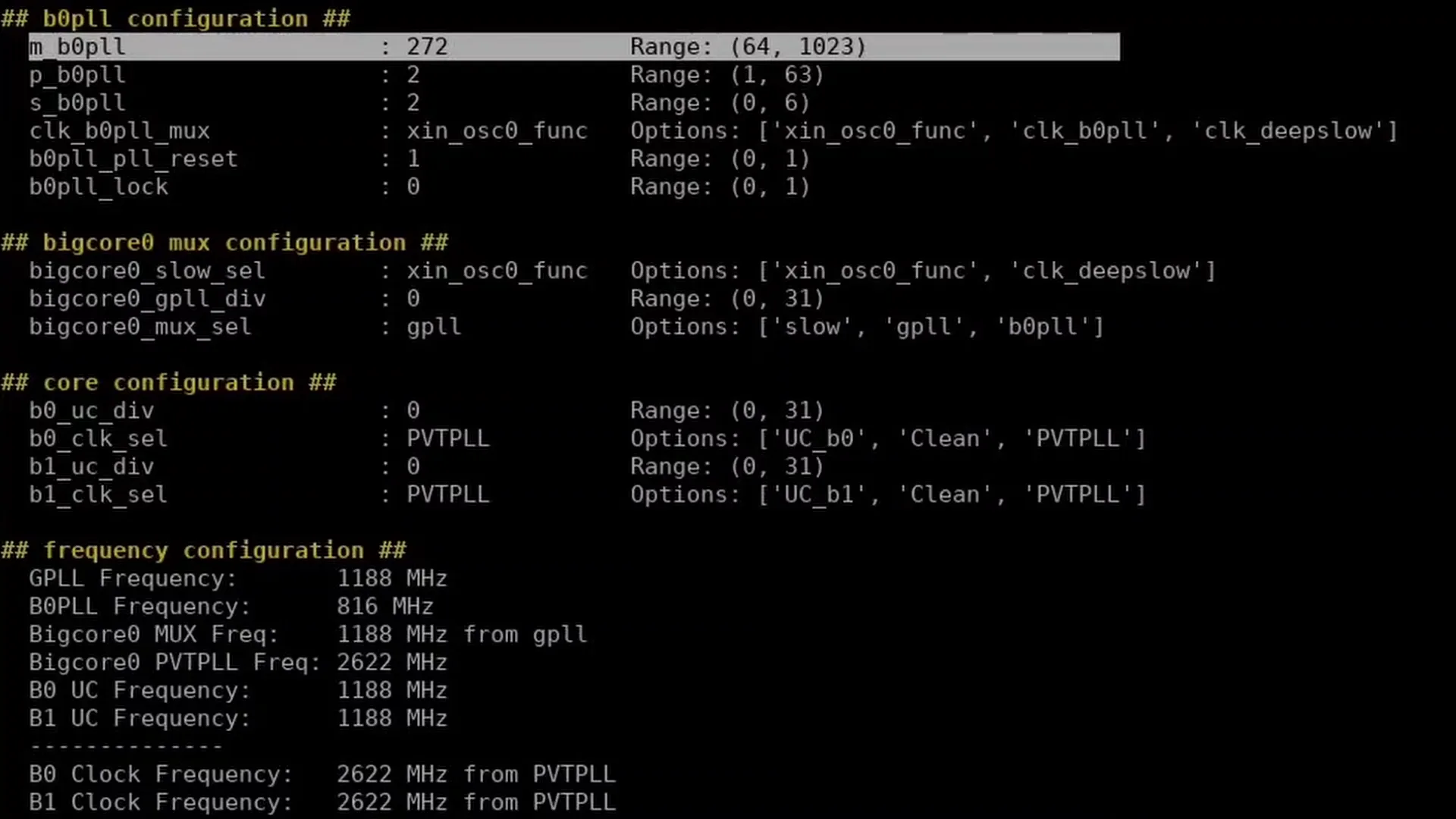
In my case, I start with a base configuration of
- m = 420
- p = 2
- s = 1 (which represents “2”)
- uc = 0 (which represents “2”)
That gives an A76 b0 core frequency of 24 MHz x 420 / 2 / 2 / 1 = 2520 MHz. Then, we can slowly walk up the multiplier ‘m’ to achieve the maximum possible frequency.
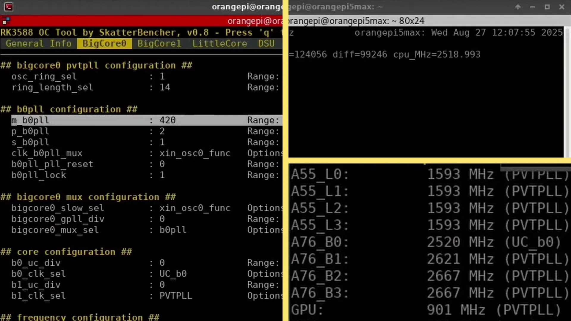
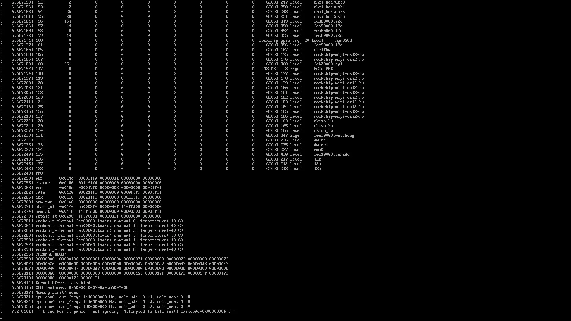
Turns out A76 Cluster 0, core 0 yields the highest operating frequency as we achieved an effective clock of 3454 MHz with multiplier ‘m’ at 576. I could set it to 578 too, yielding a frequency of 3468 MHz, but the system froze before showing the higher effective clock so I don’t count it as a valid frequency.

Rockchip RK3588 Extreme: Conclusive Thoughts
Alright, let’s wrap this up.
Cooling the Rockchip RK3588-based Orange Pi 5 Max with liquid nitrogen was pretty interesting. I was surprised to see it capable of operating for an extensive period of time under “full pot” conditions. It was even able to recover from instabilities at such low temperatures!
Of course, every SoC has its own quirks and that’s no different with the RK3588.
The main performance bottleneck, I think, is the DSU. That’s because its frequency is limited to about 2.2 GHz and its PVTPLL circuit is tied to the same voltage rail as the A55 little cores. That makes it difficult to squeeze performance in subzero conditions.
A second performance limit may be the A76 voltage limit at around 1.4V for heavy workloads. Maybe we could use an ElmorLabs Ample-X1 Power Card like we did with the Raspberry Pi 5 to push the cores with higher voltages.
But ultimately, I think there’s not much more left in this RK3588. That’s not to say we’ve hit the limit of the design. After all, there seems to be RK3588-based devices capable of running the Cortex-A76 cores at 2.4 GHz with the default 1.0V. So, hopefully, one day someone will take my overclocking tools and squeeze even more frequency out of the Rockchip RK3588.
Anyway, that’s it for this guide.
I want to thank my Patreon supporters and YouTube members for supporting my work. If you have any questions or comments, please drop them in the comment section below.
See you next time!
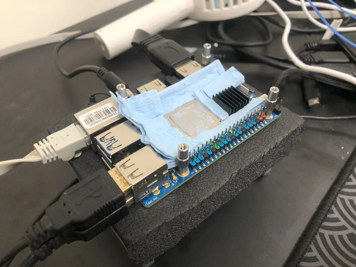
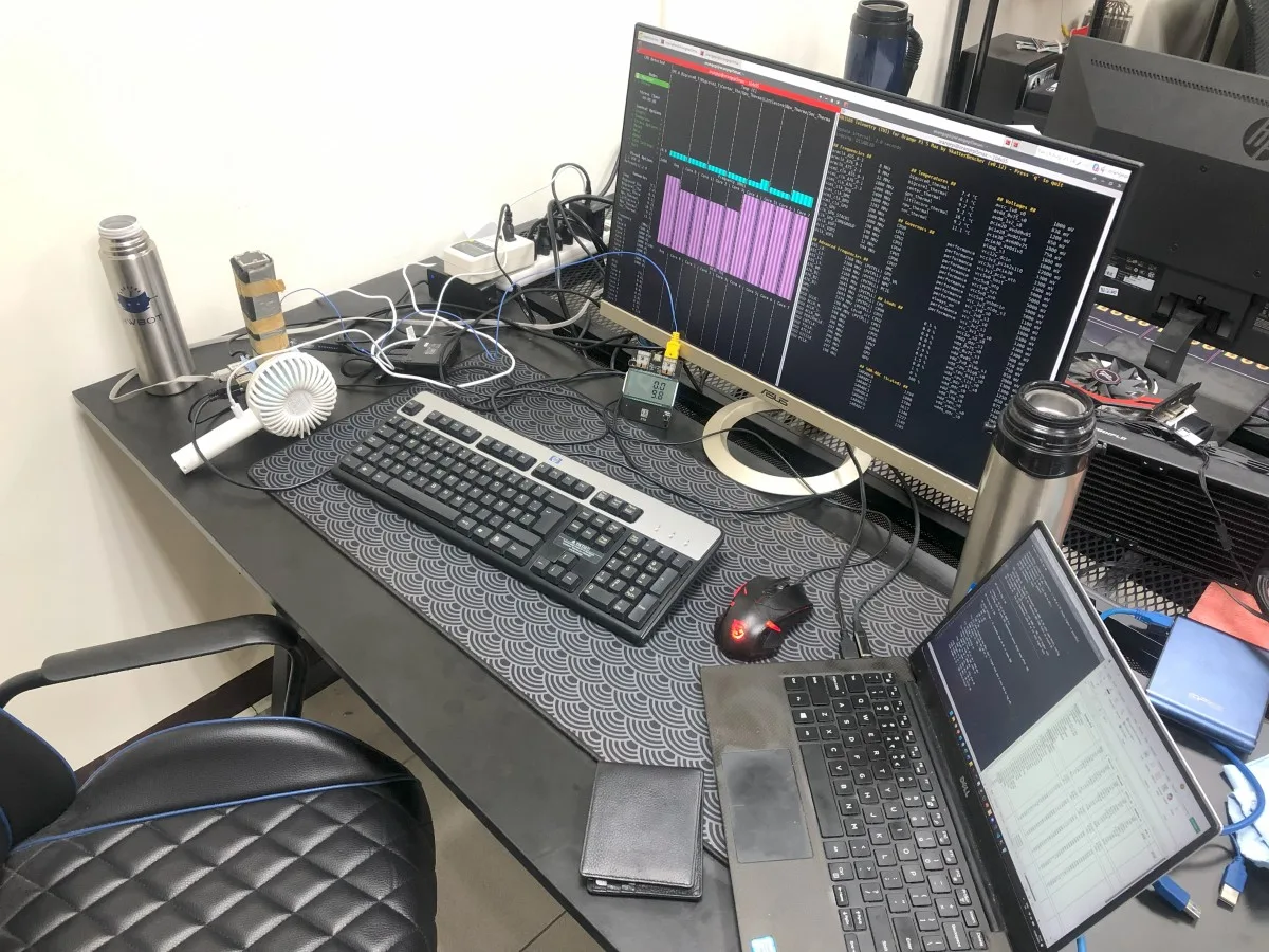
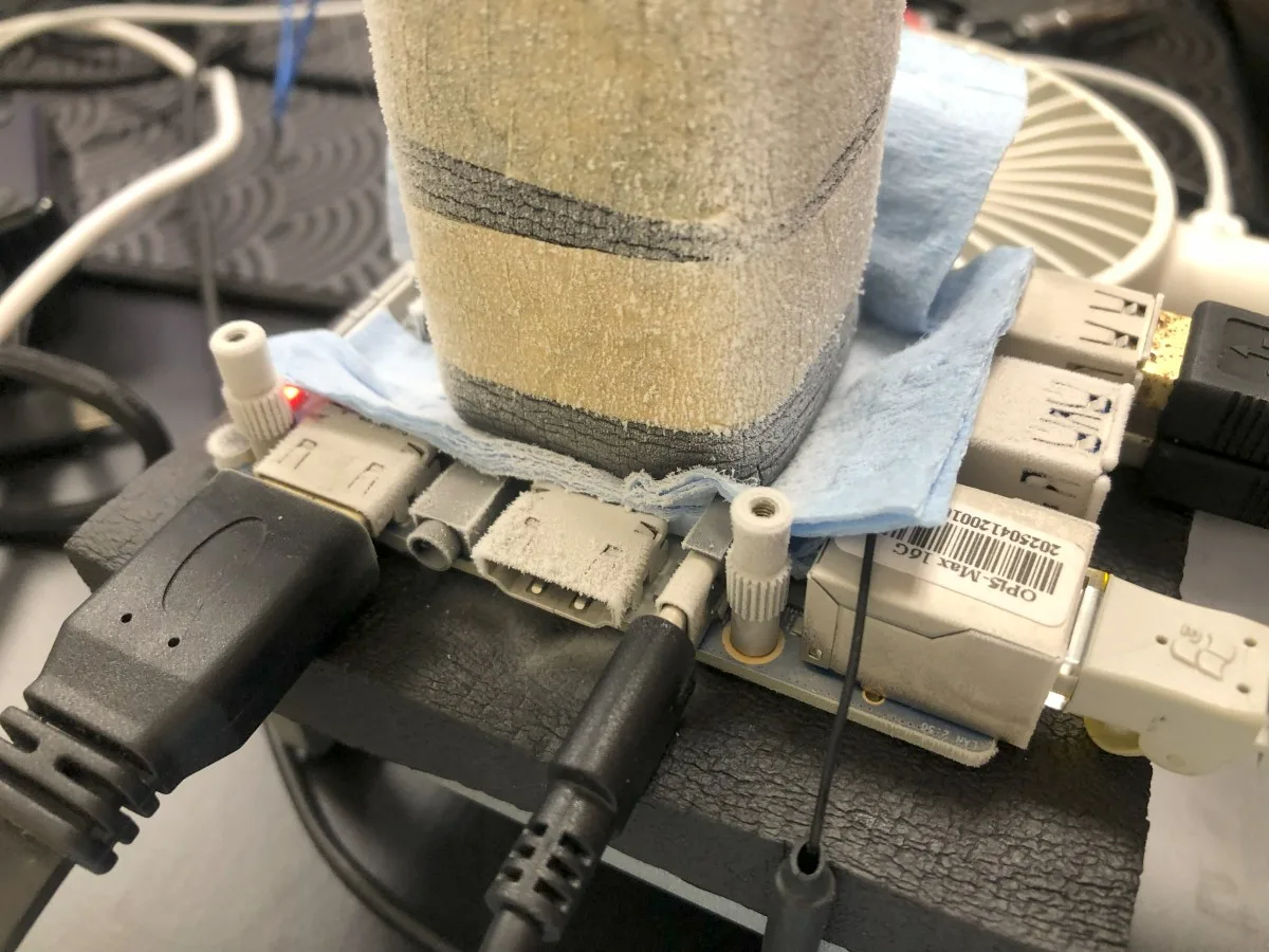
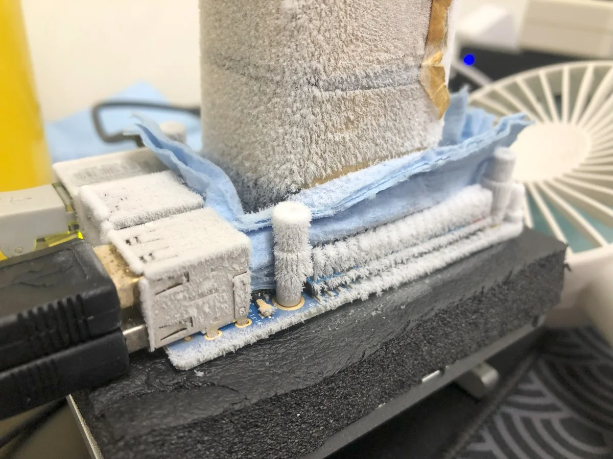
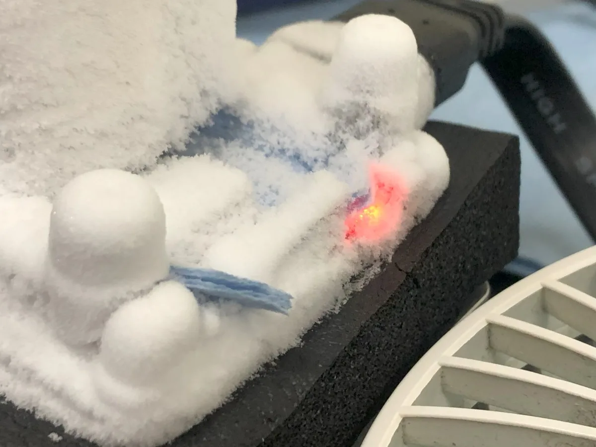
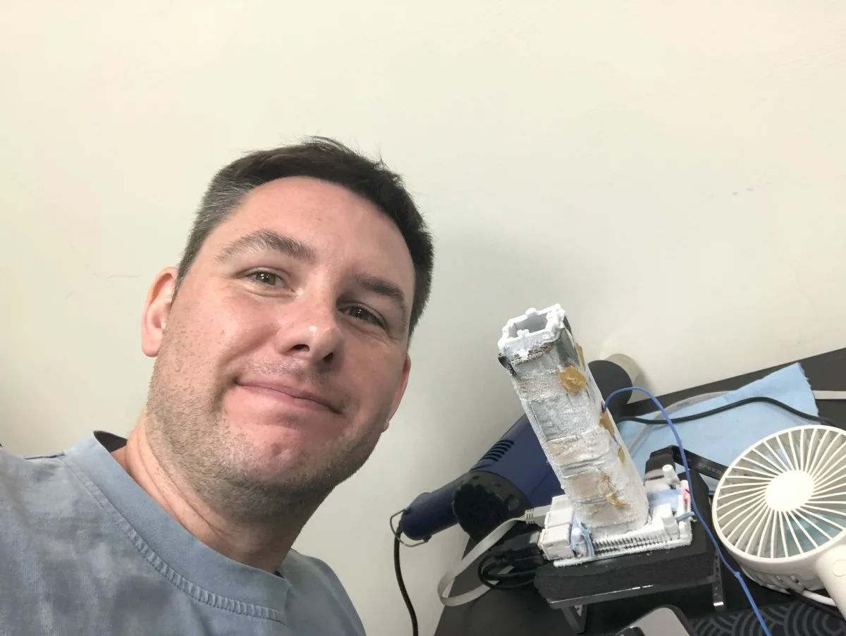
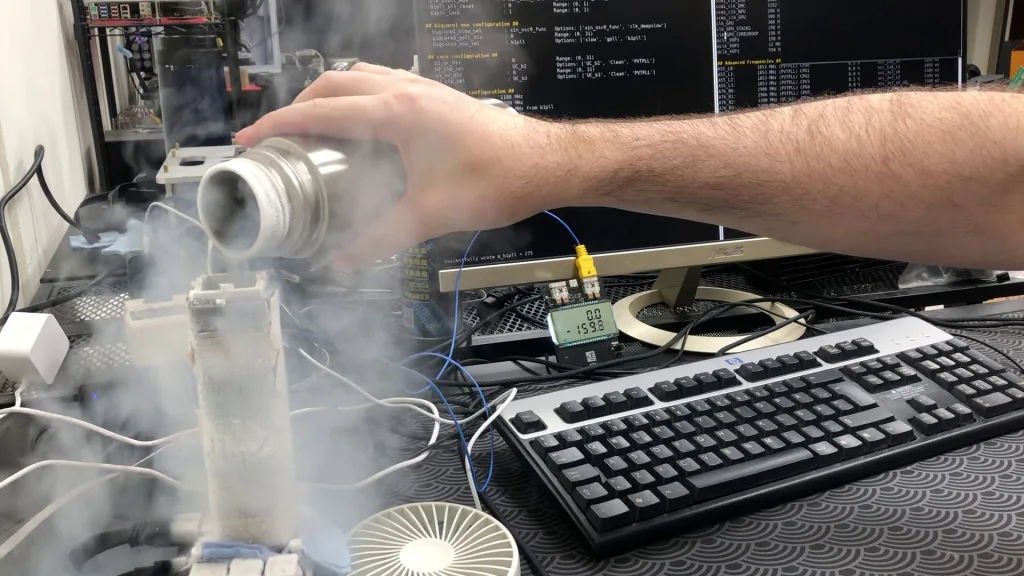
Rockchip RK3588 Extreme: Bonus Pictures
Here’s some pictures from the extreme overclocking sessions that I thought are pretty cool.
jax
Great work!
Amy chance You could implement voltage settings in your tool?
Pieter
I looked into that – possibly, but unlikely.
The chip’s voltage regulator is managed over i2C that the SoC itself uses while it’s running. That’s intentional, since the processor constantly adjusts voltage on its own depending on workload and power settings (defined in the OPP table). In theory, if the regulator exposed another control mode like PMBus, you could try to tap into it, but nothing in the documentation suggests that option is available.
Likely, the only option for direct voltage control would be like I did with Raspberry Pi 5: https://skatterbencher.com/2024/07/18/skatterbencher-77-raspberry-pi-5-overclocked-to-3000-mhz/#OC_Strategy_X_PMIC_Further_Discussion. Hook up the ElmorLabs EVC2, force the highest OPP point (avoiding SoC interference), then overriding the register value. But that’s a little more advanced than just having voltage control over I2C.