SkatterBencher #89: Orange Pi 5 Max Overclocked to 2650 MHz
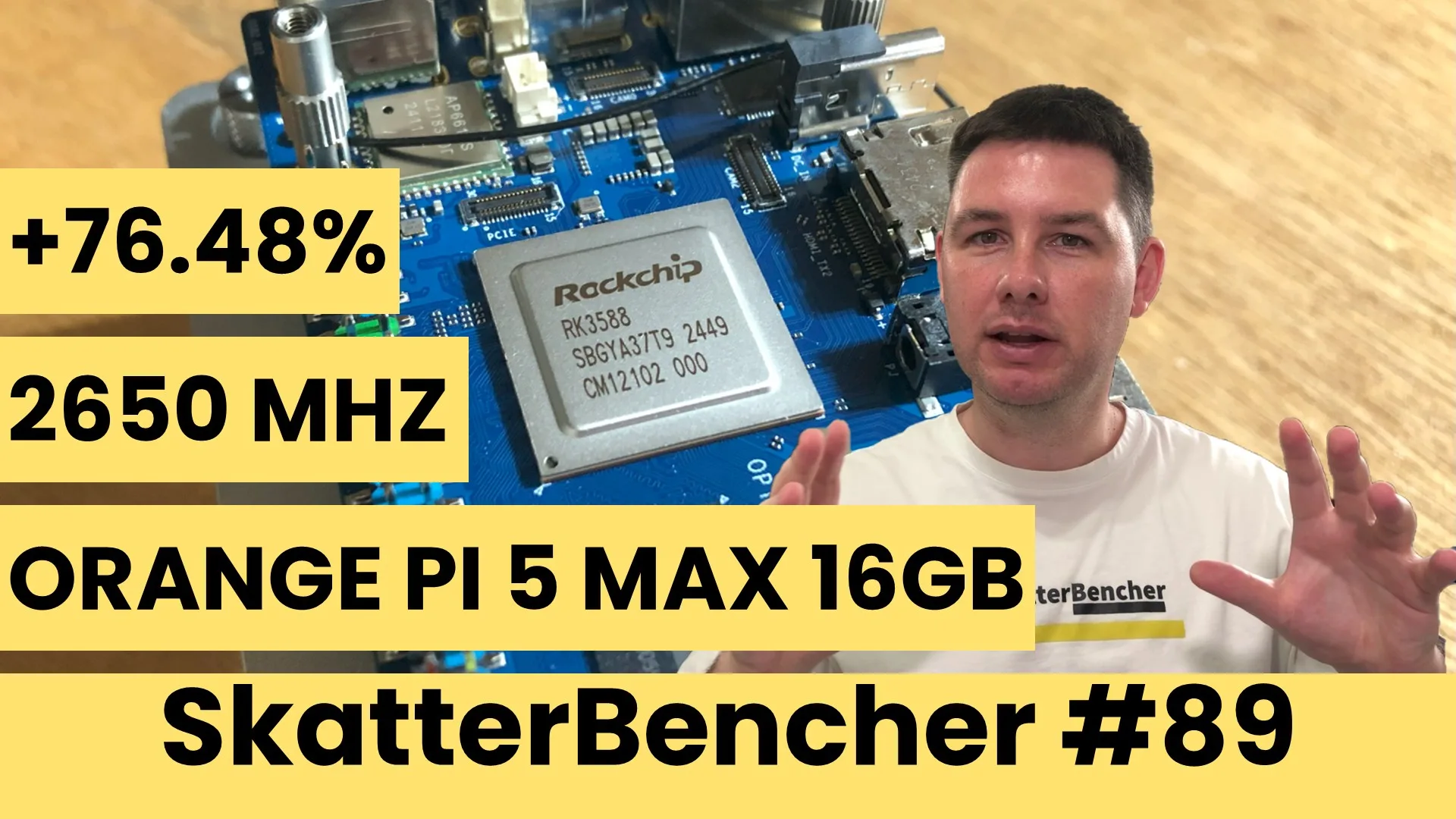
We overclock the Orange Pi 5 Max 16GB up to 2650 MHz by overvolting the PVTPLL and building custom overclocking tools.
In today’s guide, I show you how to overclock the Rockchip RK3588 SoC of the Orange Pi 5 Max single-board computer (SBC). I cover four distinct overclocking strategies, ranging from pretty simple to quite advanced:
- First, we optimize the performance governors.
- Second, increase the memory frequency.
- Third, we overvolt the PVTPLL to increase the frequency.
- Lastly, we built an overclocking tool to do manual overclocking.
However, before we jump into overclocking, let us quickly review the hardware and software used for this guide.
Orange Pi 5 Max: Introduction
The Orange Pi 5 Max is a single-board computer featuring Rockchip’s flagship RK3588 SoC. Rockchip primarily caters to edge compute and multimedia device makers, but also sells to SBC and development board companies like Banana Pi, Radxa, and Orange Pi.
The RK3588 is an 8nm SoC launched in 2022, succeeding the RK3399. It features three distinct core clusters: one quad-core cluster with Arm Cortex-A55 cores and two dual-core clusters with Arm Cortex-A76 cores. The A53 cores have an advertised maximum clock frequency of 1.8 GHz, and the A76 cores can boost to 2.4 GHz. The RK3588 also integrates the ARM Mali-G610 GPU and a dedicated NPU.
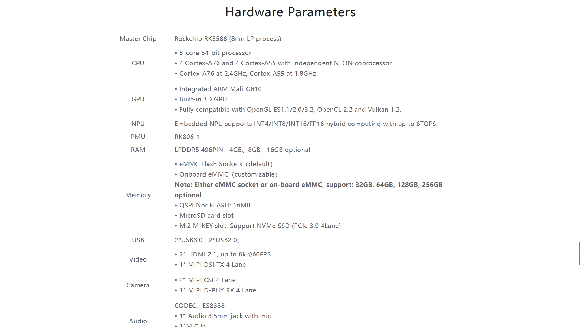
The Orange Pi 5 Max features 4, 8, or 16GB LPDDR5 memory rated up to DDR5-5500, which translates into a peak memory bandwidth of 22 GB/s. The Orange PI 5 Max supports plenty of external peripherals via various bus interfaces, including a x4 PCI-E Gen 3.0 slot.
Orange Pi 5 Max Platform Overview
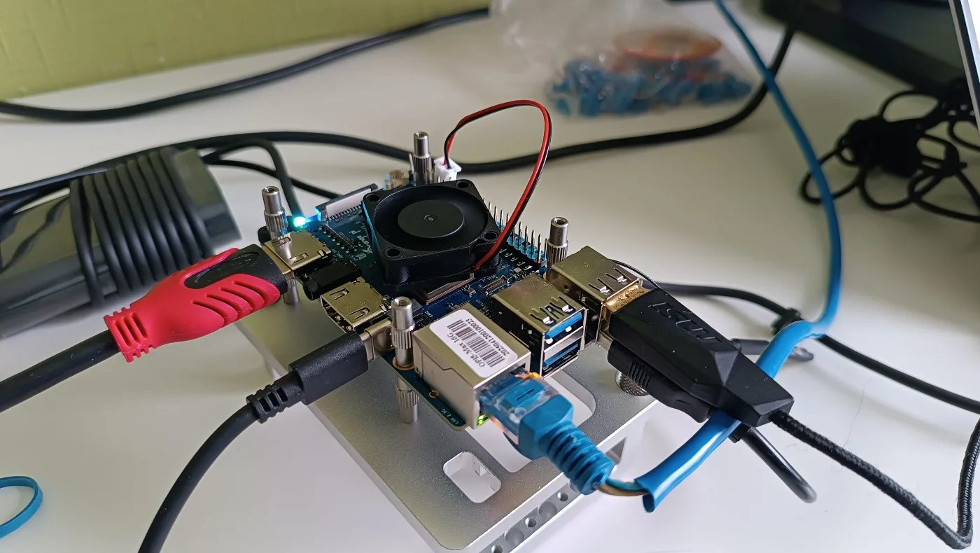
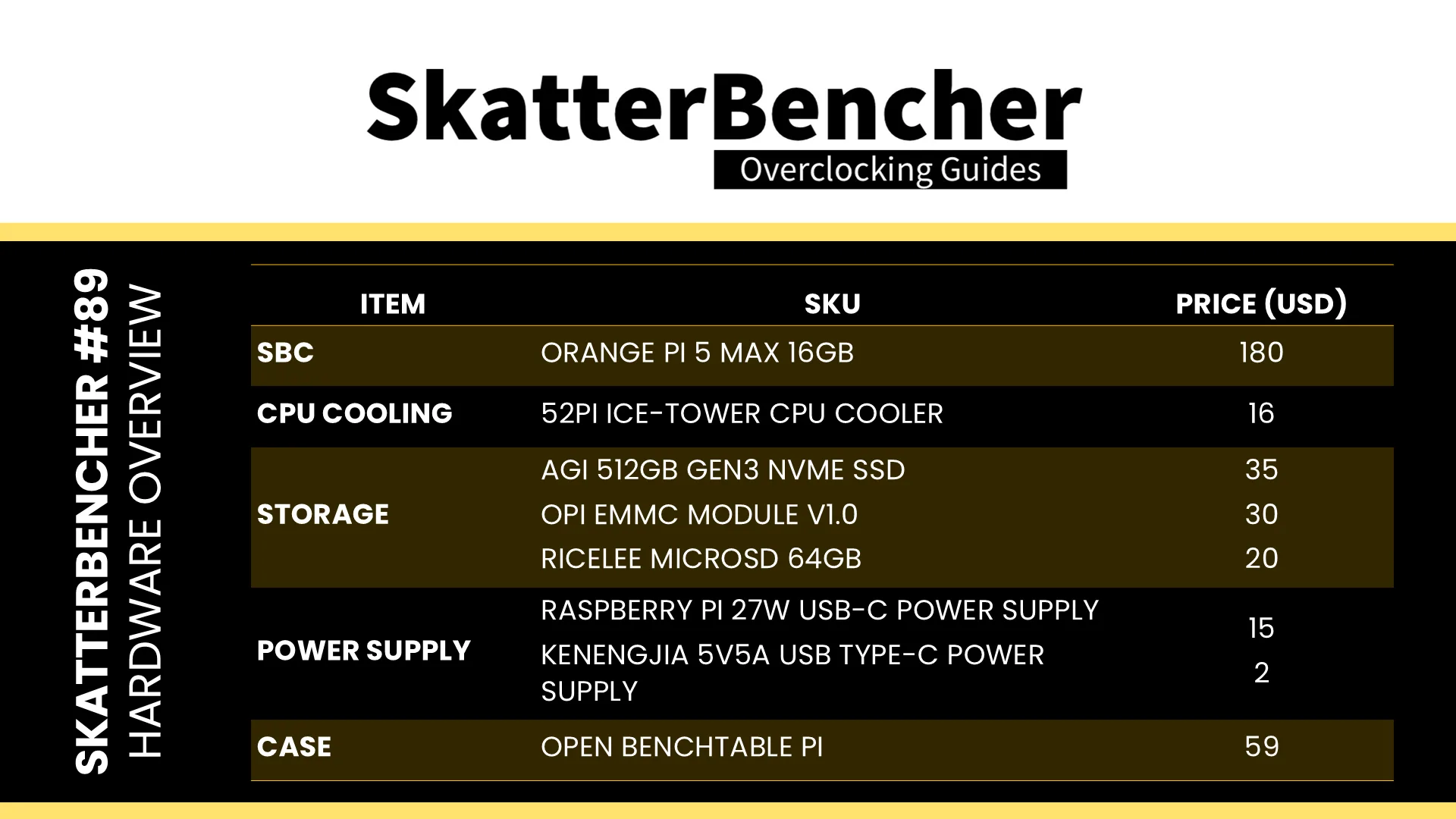
The system we’re overclocking today consists of the following hardware.
Operating System
Preparing the Orange Pi 5 Max isn’t as straightforward as our regular X86 Windows systems, mainly because of how the boot process works. There are essentially three stages:
- First, the Primary Boot Loader stored the SoC’s internal ROM (BootROM) initializes the CPU cores, basic SRAM access, and detects boot devices such as SPI Flash, eMMC, SD Card, or M.2 NVMe.
- Then, the Secondary Boot Loader on the SPI Flash (e.g., idbloader.img) initializes the LPDDR memory and loads the next stage (typically U-Boot) from the SPI itself or an external storage device like the SD card, eMMC, or M.2 NVMe.
- Lastly, the Tertiary Boost Loader (U-Boot) handles further device configuration, loads the Linux kernel, and starts the operating system.
Of course, I want to use the M.2 NVMe because it provides the highest performance.
Then, there’s the question of Linux distribution. In theory, there’s mainline support for the Orange Pi 5 Max and its Rockchip RK3588 SoC thanks to the efforts of Collabora. However, the support isn’t complete, and it looks like booting from the M.2 drive isn’t supported yet. So, I was unable to get the latest Linux kernel working.
Luckily, Orange Pi also provides a few standard images on their website. But beware that these are based on heavily modified, older Linux kernels. For example, the Debian Bookworm image is based on Linux 5.10. I picked the Debian Bullseye Desktop image, which is based on Linux 6.1.

You can read through the Orange Pi 5 Max User Manual to find out how to get the image on the device. I found that the easiest method is to use the provided RKDevTool, explained on Page 53 of the User Manual.
A couple of notes:
- To enable the English interface, open config.ini and set “Selected=2” under [Language]
- Make sure to select the rk3588_linux_pcie.cfg file for the Miniloader
- The flashing process is pretty slow since all data is transferred via the USB interface.
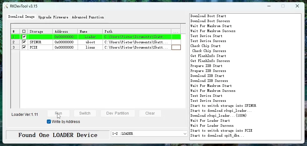
After the process is finished, the Orange Pi should automatically boot up. The default credentials are orangepi/orangepi. Of course, you can immediately update the packages using the following command: sudo apt update && sudo apt upgrade. Now we’re ready for benchmarking.
Pro-tip: I also prepared an eMMC and an SD Card with Debian Bookworm Server. Since the eMMC and SD Card are prioritized in the boot process, it’s an easy way to recover if the kernel on my NVMe drive fails.
Benchmarks & Tools
We use Debian Bullseye with Linux Kernel 6.1.43 and the following benchmark applications to measure performance and ensure system stability.
| BENCHMARK | LINK |
| Geekbench 6 (Arm Preview) | https://www.geekbench.com/preview/ |
| AI Benchmark | https://pypi.org/project/ai-benchmark/ |
| 7-Zip | https://www.7-zip.org/ |
| Sysbench | https://github.com/akopytov/sysbench |
| KCBench | https://gitlab.com/knurd42/kcbench |
| HWBOT Prime | https://github.com/SkatterBencher/benchmarks |
| Jeff Geerling’s High Performance Linpack Benchmark | https://github.com/geerlingguy/top500-benchmark |
| Openarena | https://community.hwbot.org/topic/80520-guide-3d-benchmarking-with-openarena/ |
| Passmark | https://www.passmark.com/products/pt_linux/download.php |
| GLMark2-ES2 | https://github.com/glmark2/glmark2 |
| PIBenchmarks | https://pibenchmarks.com/ |
| Tinymembench | https://github.com/ssvb/tinymembench |
| SBC Bench | https://github.com/ThomasKaiser/sbc-bench |
| S-tui | https://github.com/amanusk/s-tui |
I mostly use the command line terminal to run these benchmarks, so it’s not as easy as on Windows. I’ll put up a how-to for the benchmarks on my blog if you want to run them as well.
Notes:
- The HPL Benchmark runs the default configuration from Jeff Geerling’s Orange Pi 5 Max review
- OpenArena runs on the CPU cores using LLVMPipe due to some issues operating the Mali GPU in OpenGL.
- GLMark2-ES2 is running on the Mali GPU.
- While I picked S-tui as the stress test, it is not the worst-case workload. It uses significantly less power than AI Benchmark or Jeff Geerling’s HPL Benchmark.
I use the following tools to flash the drives, log telemetry, and adjust clock frequencies.
| TOOLS | LINK |
| RKDevTool v3.15 | https://drive.google.com/drive/folders/1DQv_OoJvMRIQDsKskkb75hBUnUTr1HS0 |
| Win32DiskImager v1.0 | https://sourceforge.net/projects/win32diskimager/ |
| Willy Tarreau’s “mhz” | https://github.com/wtarreau |
| Boogiepop’s “mmm” | https://github.com/hbiyik/mmm |
| Boogiepop’s RKDDR | https://github.com/hbiyik/rkddr |
| RK3588 Telemetry | https://github.com/SkatterBencher/rk3588-tools/ |
| RK3588 OC Tool | https://github.com/SkatterBencher/rk3588-tools/ |
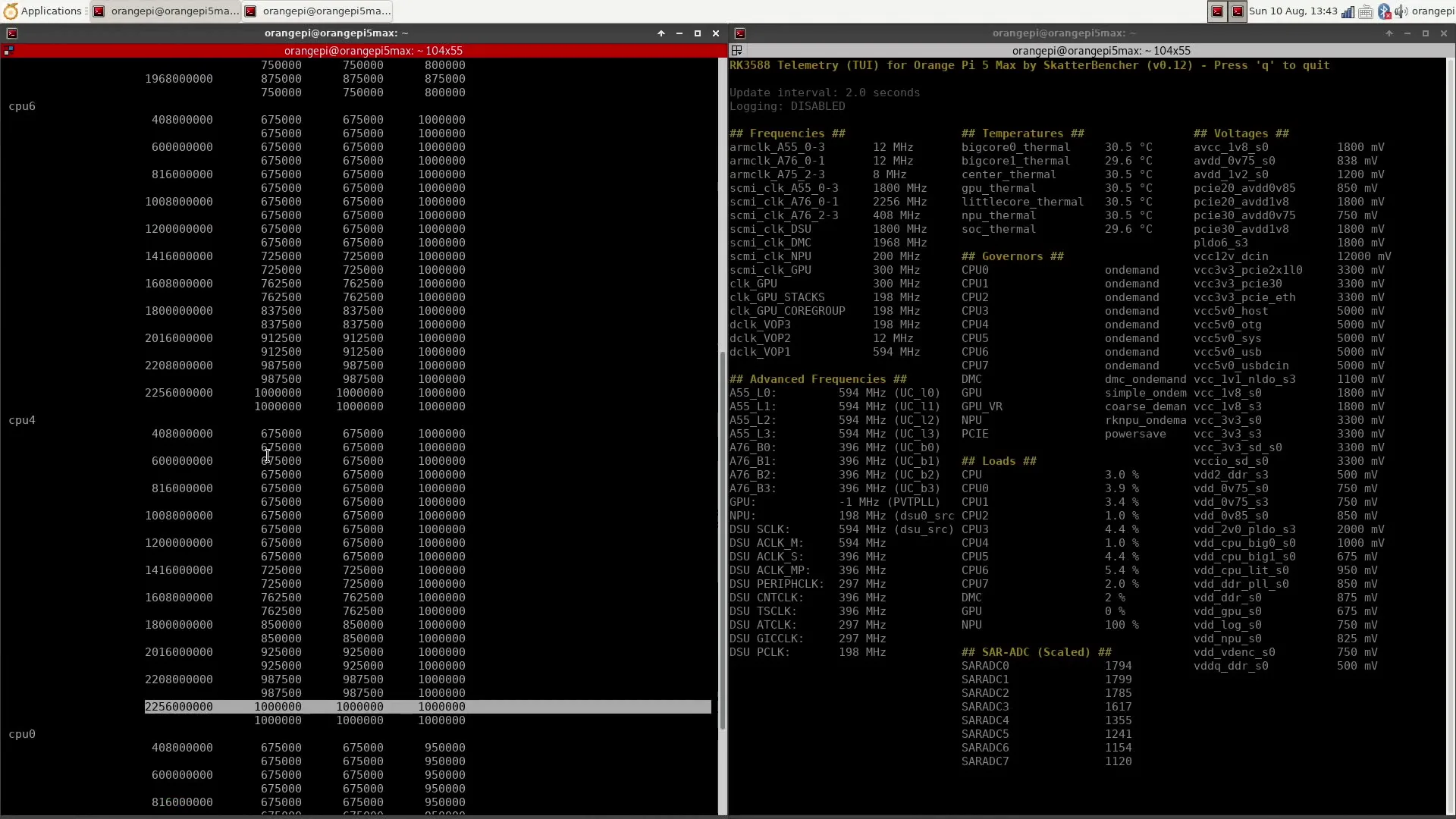
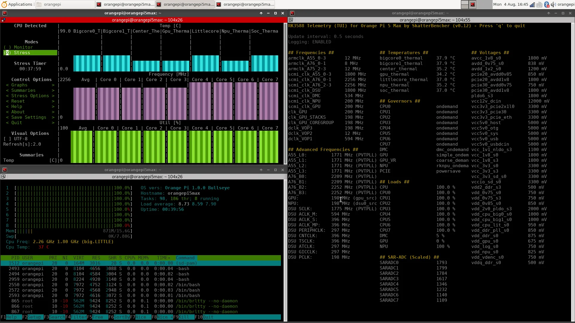
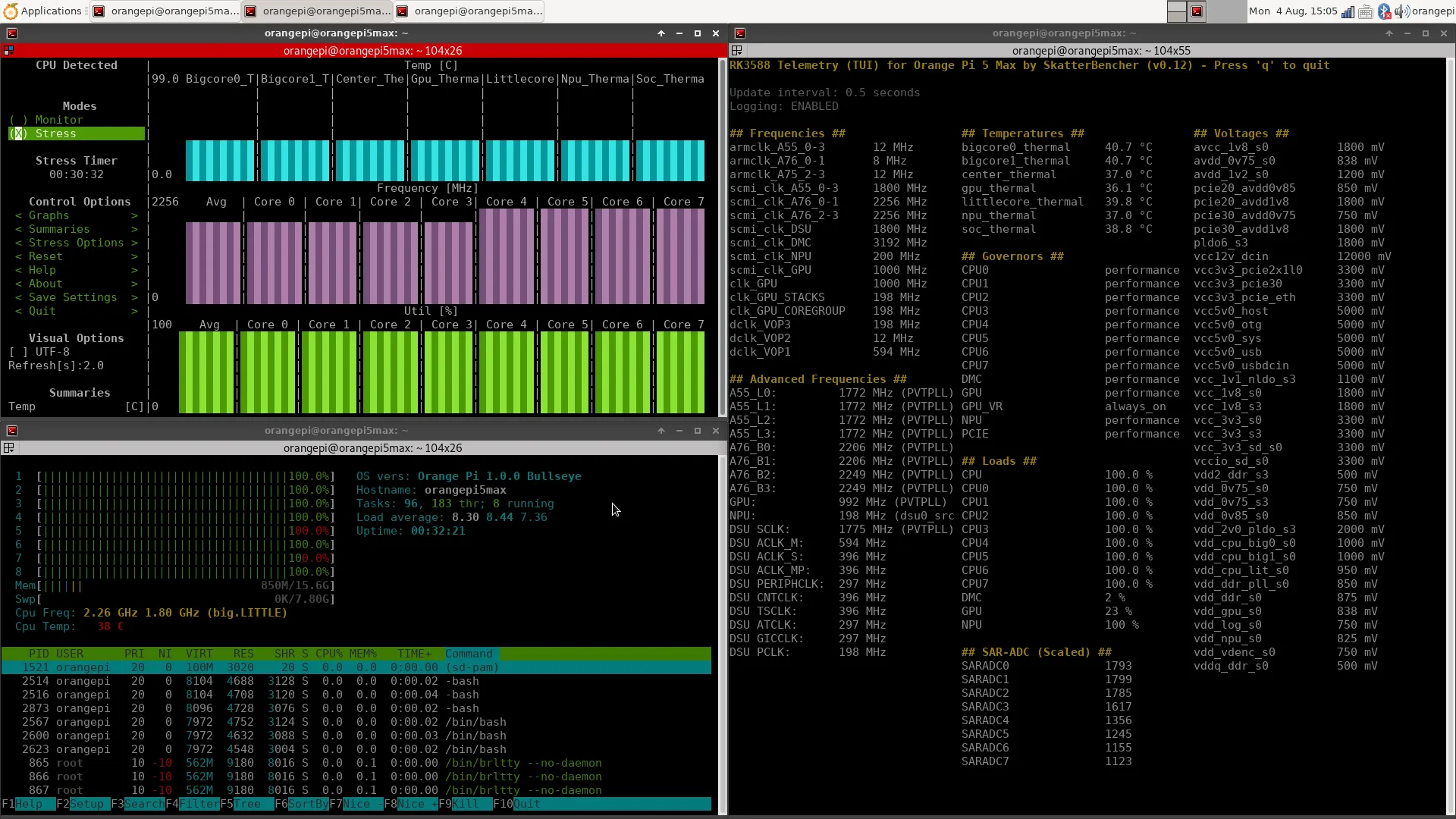
Telemetry Monitoring & Logging
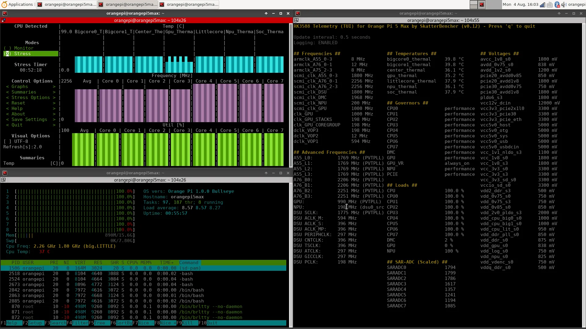
A quick couple of words on the RK3588 Telemetry tool I built for this project. The key point to understand about telemetry is that what we see in software isn’t always what the hardware is doing. That’s particularly relevant for operating frequency, voltage, and temperature.
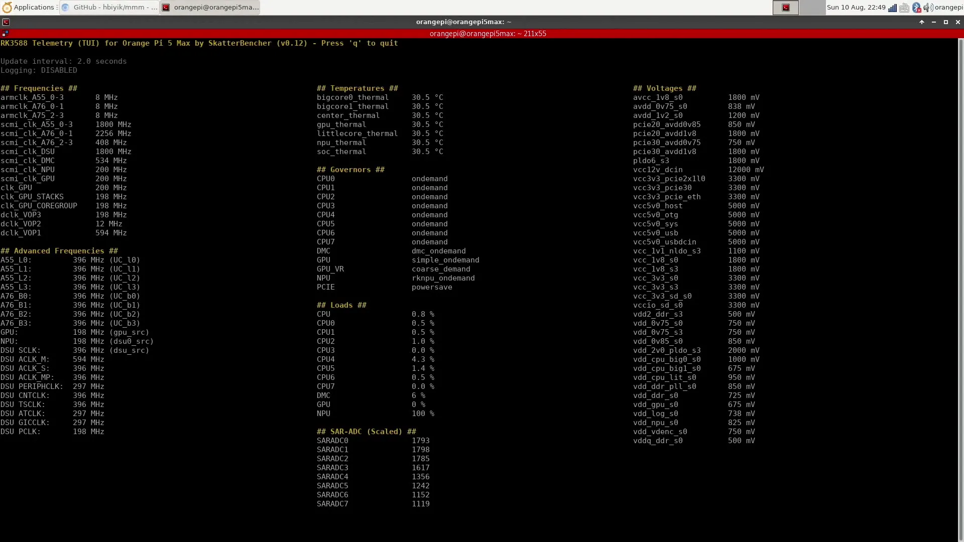
For the operating frequency monitoring, I rely on the data from the Rockchip RK3588 Technical Reference Manual (TRM). We can access a lot of registers, including those to accurately calculate the operating frequencies of various IP blocks.
I also want to give a shout-out to Willy Tarreau, creator of the CPU frequency measurement tool appropriately called “mhz”. It’s a simple but incredibly useful tool that runs long loops of XOR operations that run at a rate of one operation per clock cycle. That gives us a way to indirectly measure CPU frequency and helps us validate what we’re seeing from the CPU registers.
Also, a quick shout-out to Boogiepop or hbiyik for sharing his mmm tool with the Radxa community. This tool also accesses the SoC registers and was a great help to verify data when I built my tools.
For the operating temperature monitoring, I rely on the information from the /sys/class/hwmon/hwmon* directory. This maps directly to the seven (7) channel Temperature-Sensor ADC (TS-ADC) of the RK3588.
For the operating voltage monitoring, I rely on the information from the /sys/class/regulator/regulator.* directory. This provides information about the configuration of the three voltage regulators (RK806 PMIC and 2x RK860 DC/DC). However, it doesn’t provide real-time telemetry data.
Unfortunately, it looks like neither of the voltage regulators supports real-time telemetry via the I2C interface. So, the only way to verify the voltage in real time is to measure from the PCB. I mapped out the voltage measurement points in case anyone is interested.
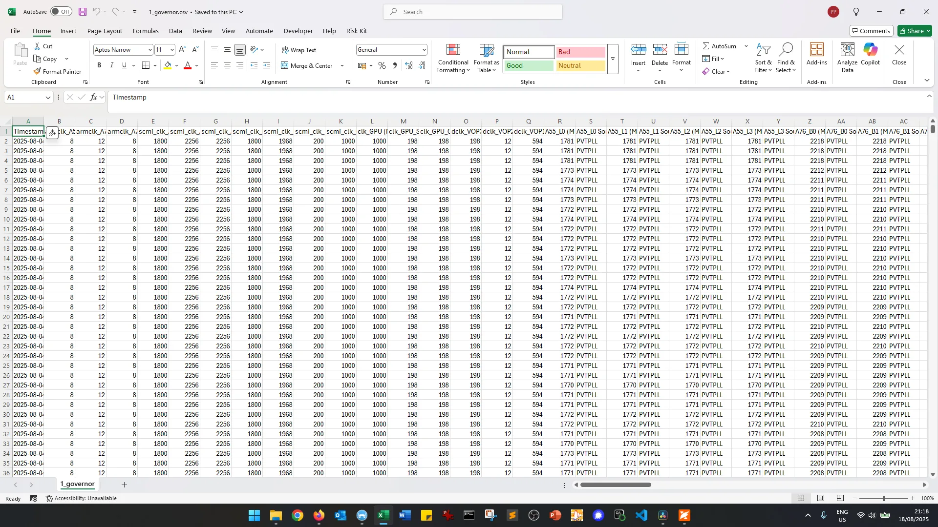
Just like the Raspberry Pi 5 telemetry tool we built a while ago, this tool supports logging to a CSV file for further analysis.
Orange Pi 5 Max: Stock Performance
Before starting overclocking, we must check the system performance at default settings. The default operating frequencies for the Orange Pi 5 Max are as follows.
- ARM Cortex-A55 cluster: 1785 MHz
- ARM Cortex-A76 cluster0: 2222 MHz
- ARM Cortex-A76 cluster1: 2270 MHz
- DSU SCLK: 1790 MHz
- DMC: 1968 MHz
- GPU: 990 MHz
- NPU: 198 MHz
A quick word on frequency of the Cortex-A76 clusters: while it’s advertised to run at 2.4 GHz, its highest Operating Performance Point (or OPP) is only 2256 MHz.
- sudo cat /sys/kernel/debug/opp/opp_summary
This is a known “issue” for RK3588-based devices, as different SBCs may have a different maximum frequency.
Furthermore, the actual operating frequency is determined by an adaptive clocking technology called PVTPLL, where PVT stands for Process-Voltage-Temperature. So, the actual effective clock is not exactly 2256 MHz. I’ll discuss PVTPLL in depth in the third overclocking strategy.
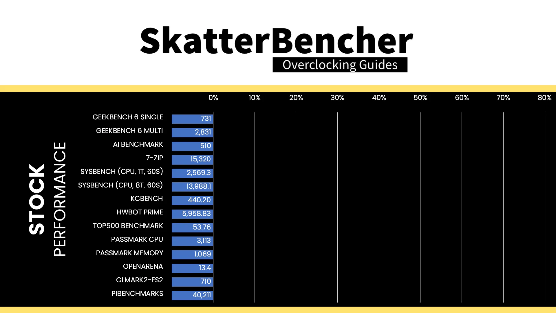
Here is the benchmark performance at stock:
- Geekbench 6 (Single): 731 points
- Geekbench 6 (Multi): 2,831 points
- AI Benchmark: 510 points
- 7-Zip: 15, 230 mips
- Sysbench (1T, 60S): 2569.3 events / second
- Sysbench (4T, 60S): 13,988.1 events / second
- KCBench (1 run, -J8): 440.20 seconds
- HWBOT Prime: 5958.83 points
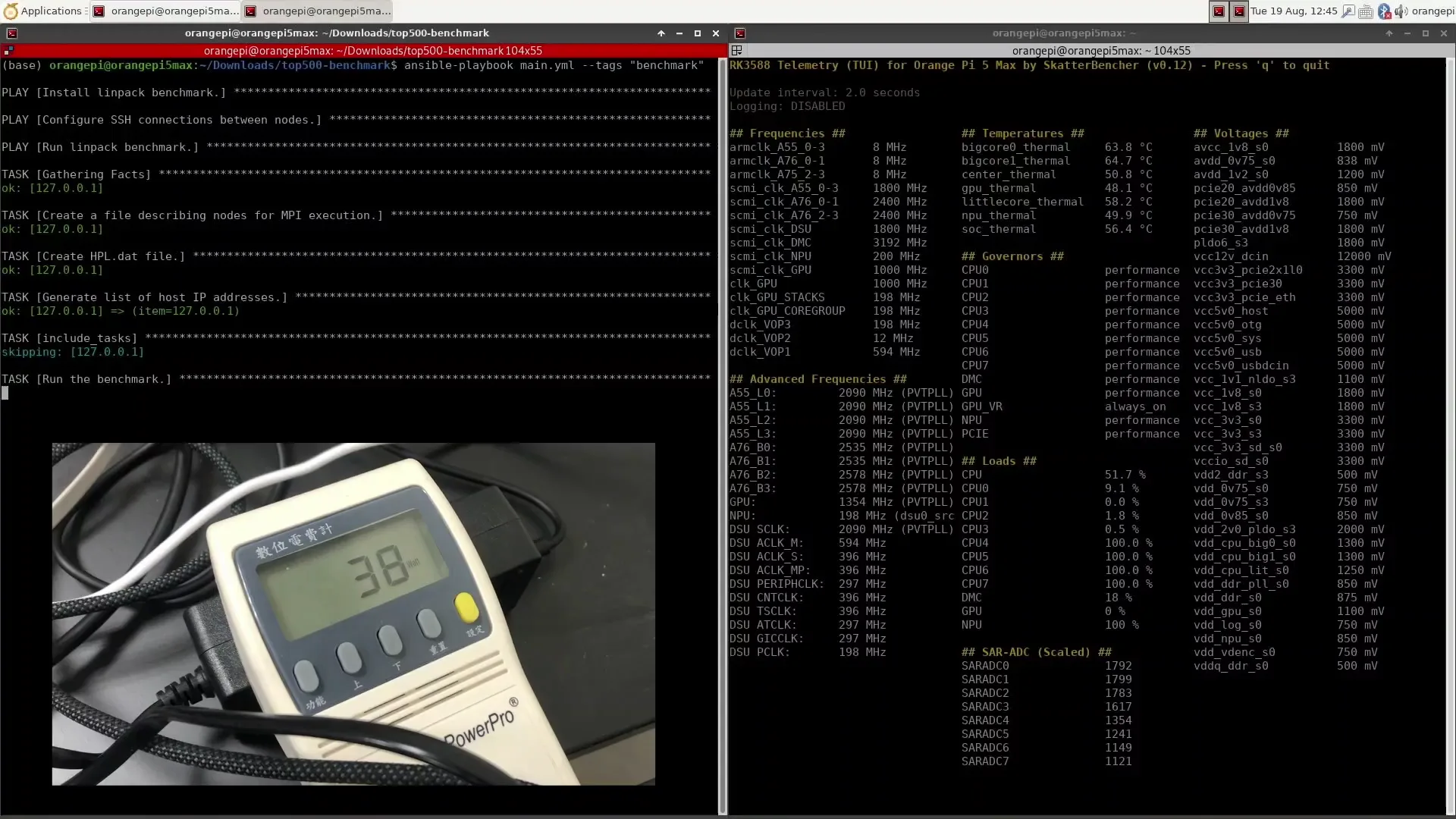
- Top500 Benchmark: 53.76 GFlops
- Passmark (CPU): 3,133 marks
- Passmark (Memory): 1069 marks
- Openarena (CPU): 13.4 fps
- GLMark2-ES2 (GPU): 710 marks
- PIBenchmarks: 40,211 points
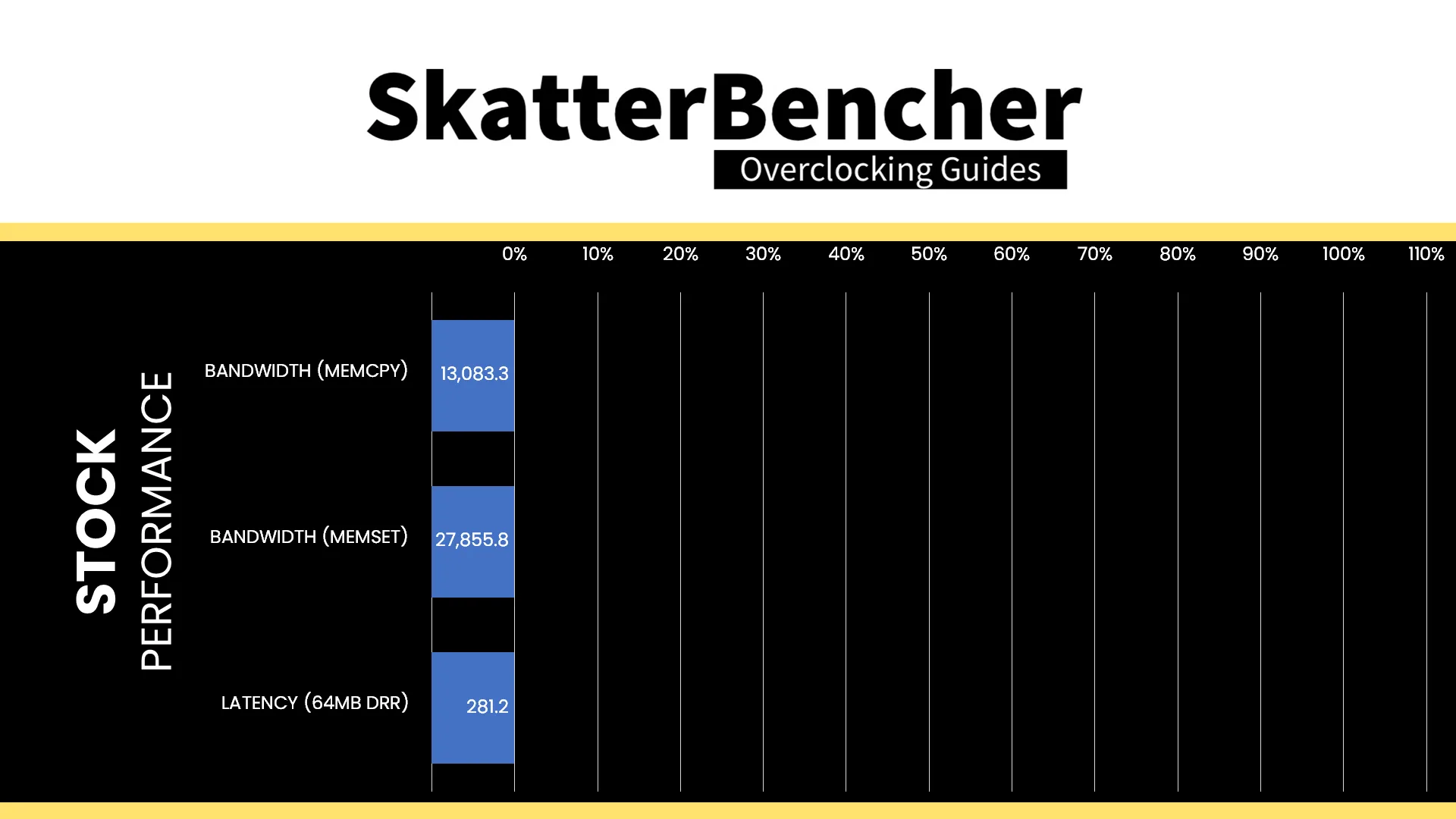
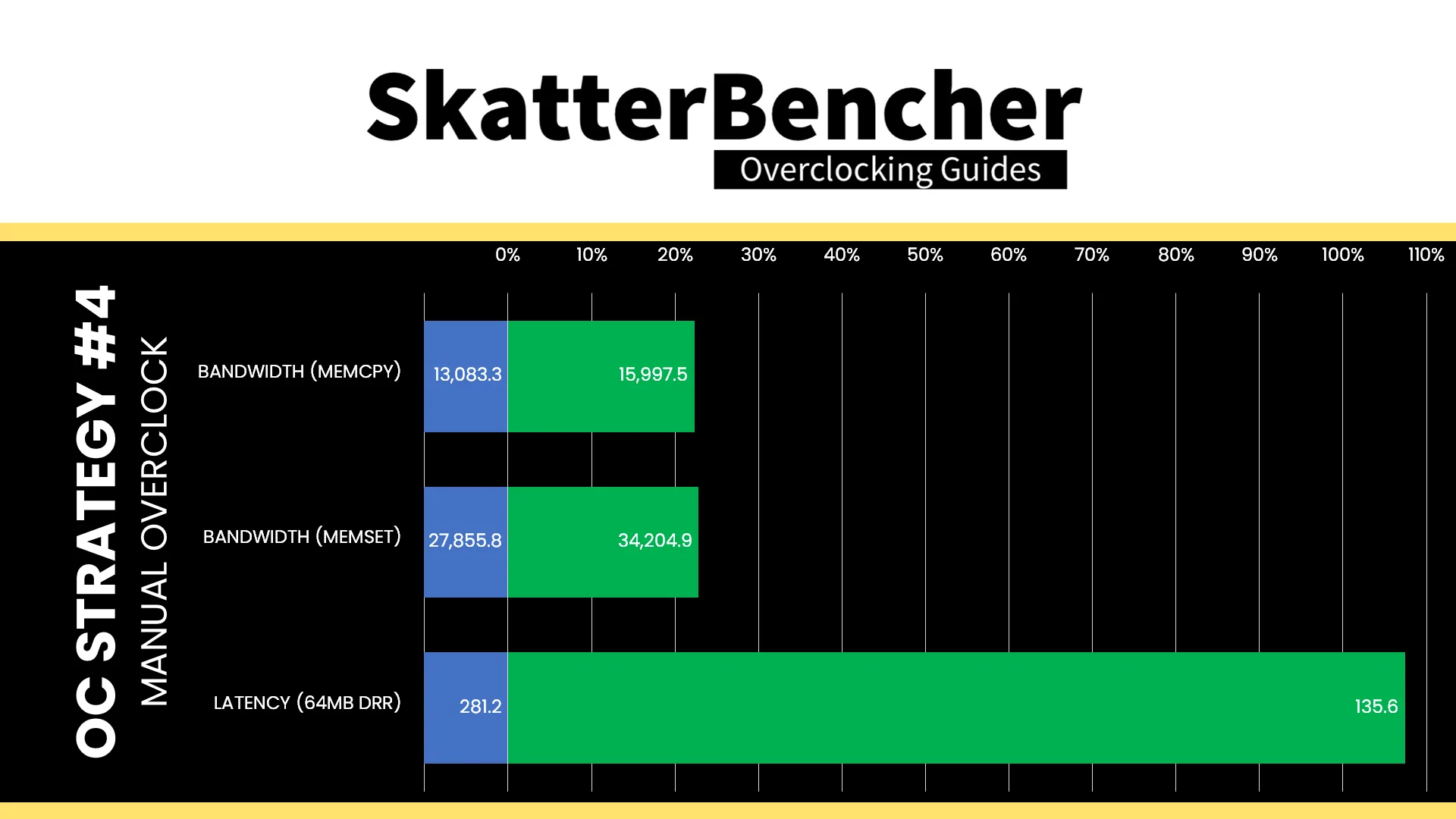
- Tinymembench (MEMCPY): 13,083.3 MB/s
- Tinymembench (MEMSET): 27,855.8 MB/s
- Tinymembench (64MB DRR): 281.2 ns
When running the S-TUI Stability Test, the average A55 Cluster clock is 1771 MHz with 0.950 volts, the average A76 Cluster0 clock is 2209 MHz with 1.000 volts, and the average A76 Cluster1 clock is 2252 MHz with 1.000 volts. The average SoC temperature is 37.0 degrees Celsius. The approximate wall power consumption is 10 watts.
OC Strategy #1: Performance Governors
In our first overclocking strategy, we’re not quite increasing the operating frequencies just yet. Instead, we first have a look at the performance governors and optimize them for performance.
Performance Governors
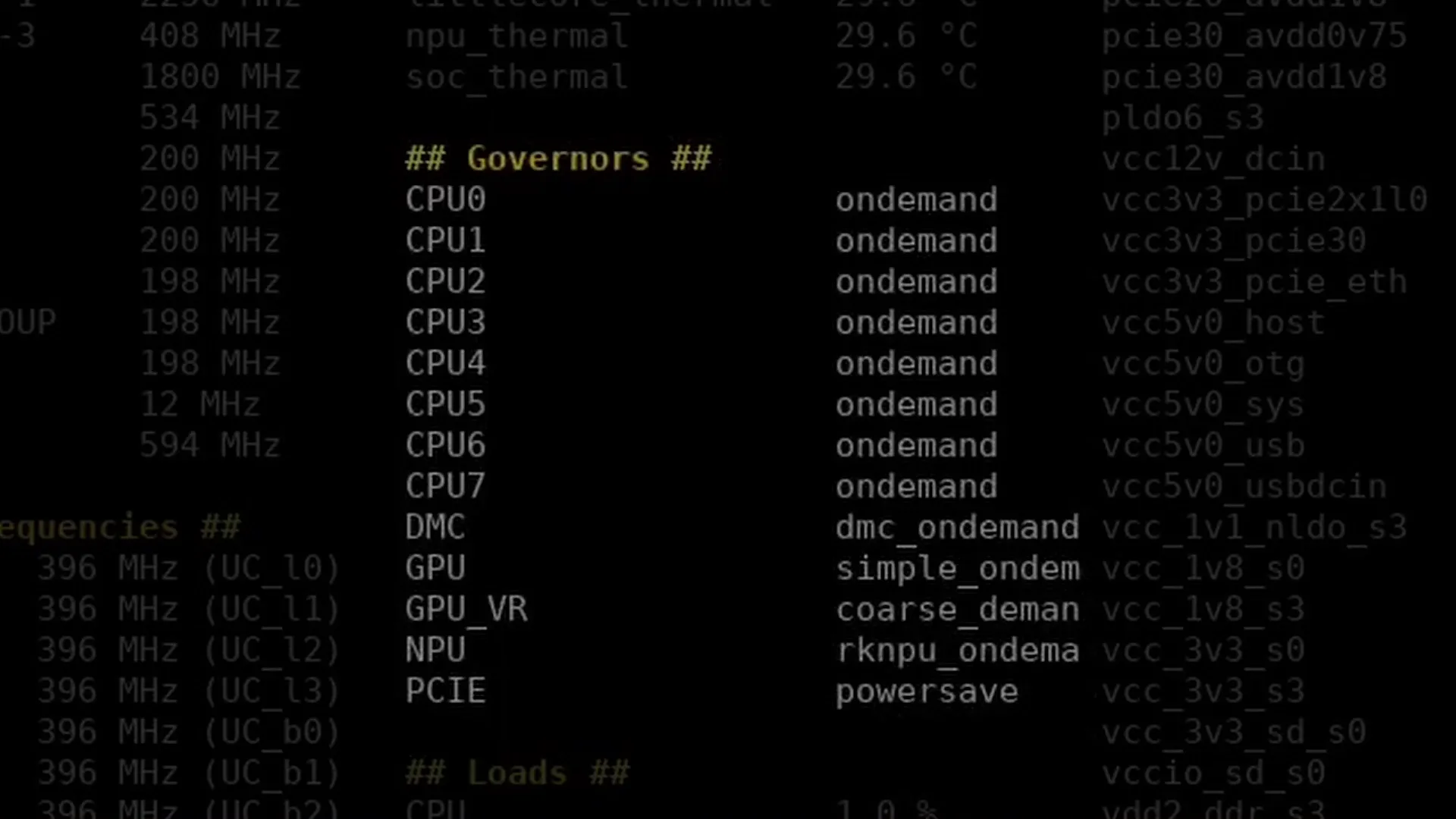
Performance governors allow various IP blocks to adjust the operating frequency and voltage according to the workload needs. Since SoCs like the RK3588 are mostly used in mobile or embedded applications, the governors are out-of-the-box configured to balance performance and power consumption. However, in our case, we’re looking to maximize the performance of this single-board computer.
The Orange Pi 5 Max has governors for the following IP blocks: the CPU cores, DMC, GPU, NPU, and PCIE ASPM.
I first became aware of the importance of optimizing the governors for SBCs by reading through Tkaiser’s extensive preview of the RK3588-based Rock 5B SBC. I strongly recommend checking out his sbc-bench tool to better understand the importance of tuning the governors.
Checking the governor configuration is pretty straightforward using the following commands or my telemetry tool.
- cat /sys/devices/system/cpu/cpu*/cpufreq/scaling_governor
- cat /sys/devices/platform/dmc/devfreq/dmc/governor
- cat /sys/devices/platform/fb000000.gpu/devfreq/fb000000.gpu/governor
- cat /sys/devices/platform/fb000000.gpu/devfreq/fb000000.gpu/device/power_policy
- cat /sys/devices/platform/fdab0000.npu/devfreq/fdab0000.npu/governor
- cat /sys/module/pcie_aspm/parameters/policy
Configuring the Governors
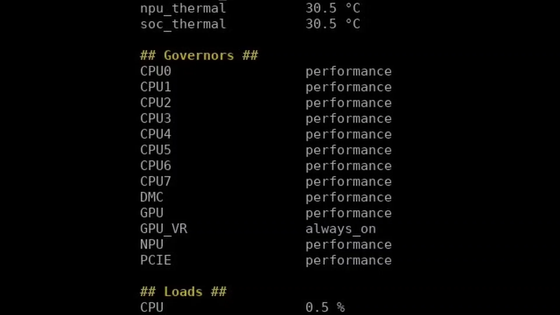
Configuring the governors is pretty straight-forward. Simply echo “performance” or “always_on” to switch the governor to the highest Performance setting.
- echo performance | sudo tee /sys/devices/system/cpu/cpu*/cpufreq/scaling_governor
- echo performance | sudo tee /sys/devices/platform/dmc/devfreq/dmc/governor
- echo performance | sudo tee /sys/devices/platform/fb000000.gpu/devfreq/fb000000.gpu/governor
- echo always_on | sudo tee /sys/devices/platform/fb000000.gpu/devfreq/fb000000.gpu/device/power_policy
- echo performance | sudo tee /sys/devices/platform/fdab0000.npu/devfreq/fdab0000.npu/governor
- echo performance | sudo tee /sys/module/pcie_aspm/parameters/policy
Each of the IP blocks should now be running at its highest performance setting, with the trade-off being increased power consumption.
Performance Governor Service
For my system, I wanted to have these settings apply on boot so the SBC would always run at maximum performance. So, I created a small service. Here’s how you create this service:
First, create a file with the commands in /bin/ called opi5perf
echo performance | tee /sys/devices/platform/dmc/devfreq/dmc/governor
echo performance | tee /sys/devices/platform/fb000000.gpu/devfreq/fb000000.gpu/governor
echo always_on | tee /sys/devices/platform/fb000000.gpu/power_policy
echo performance | tee /sys/devices/platform/fdab0000.npu/devfreq/fdab0000.npu/governor
echo performance | tee /sys/module/pcie_aspm/parameters/policy
echo performance | tee /sys/devices/system/cpu/cpu*/cpufreq/scaling_governor
Then, create the service to execute our governor commands in /etc/systemd/system/ (e.g., opi5perf.service
[Unit]
Description=Set all governors to Performance
After=multi-user.target
Requires=multi-user.target

[Service]
Type=oneshot
ExecStart=/bin/bash /bin/opi5perf

[Install]
WantedBy=multi-user.target
Then enable the system service: sudo systemctl enable opi5perf.service
You can try out the service with “sudo systemctl start opi5perf.service” and check if there are any errors with “journalctl -xe”.
Now the performance governors should be configured automatically at boot.
For your convenience, I’ve also uploaded the scripts to my GitHub page.
Benchmark Results
We rerun the benchmarks and check the performance increase compared to the default operation.
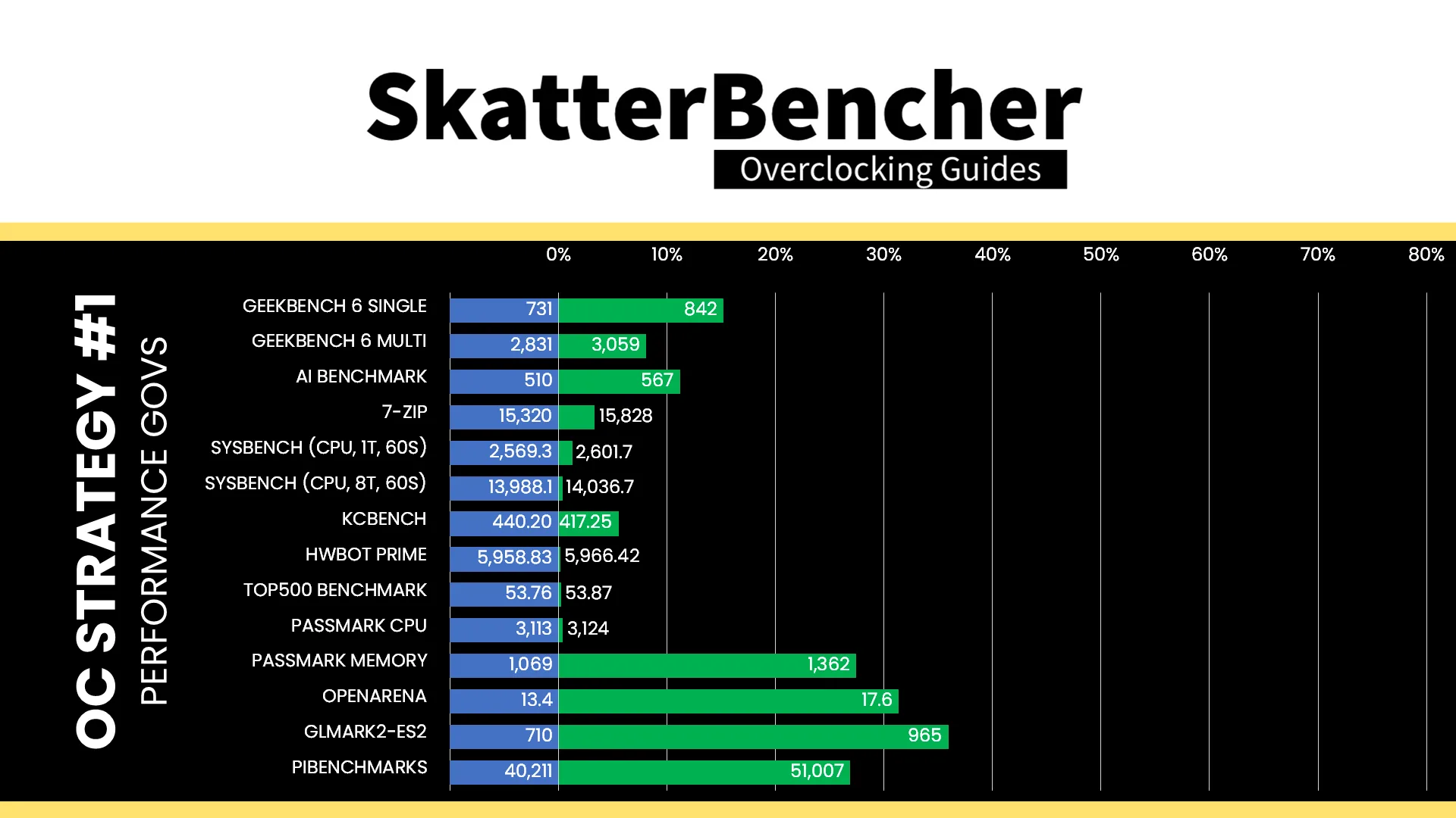
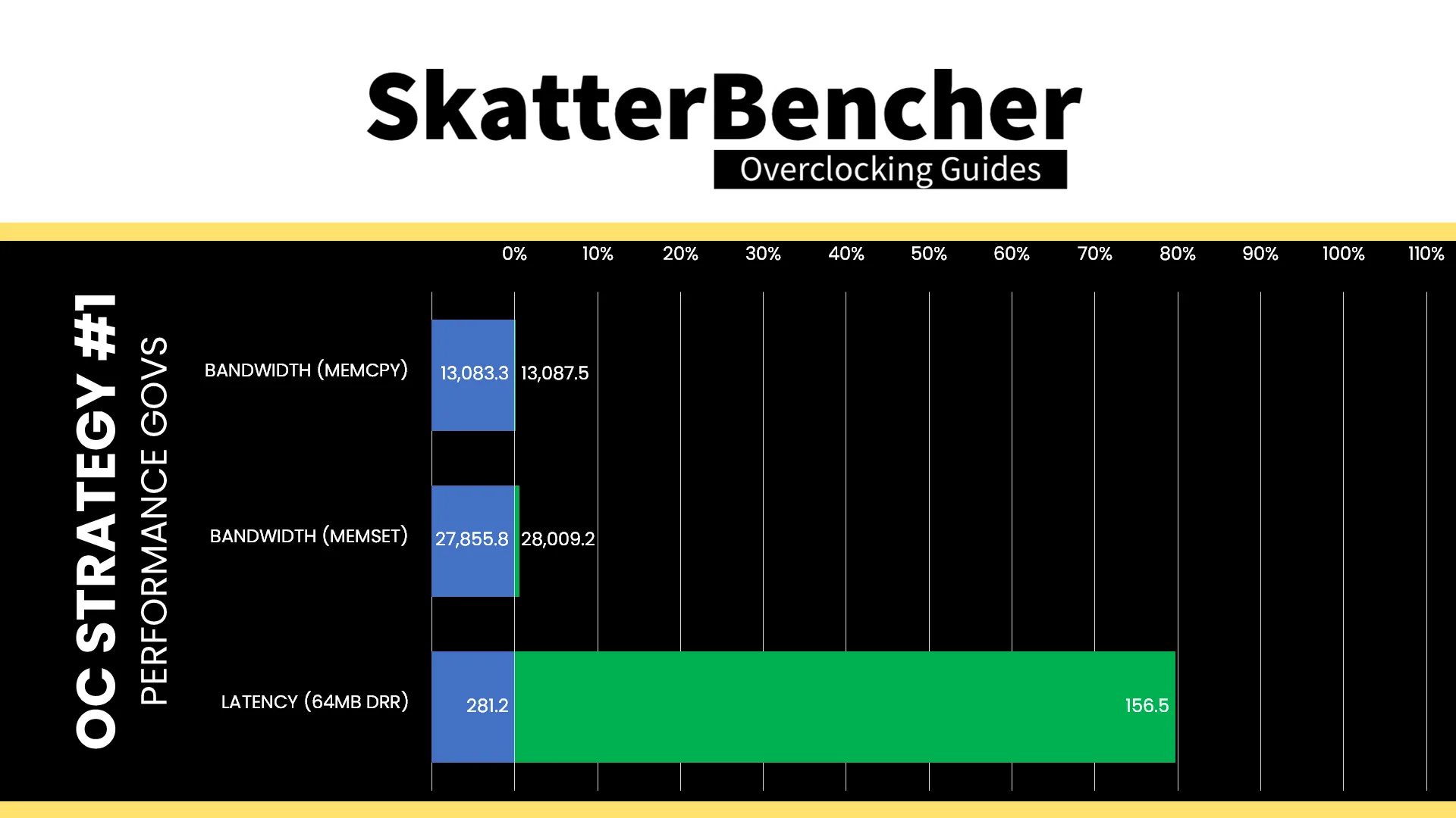
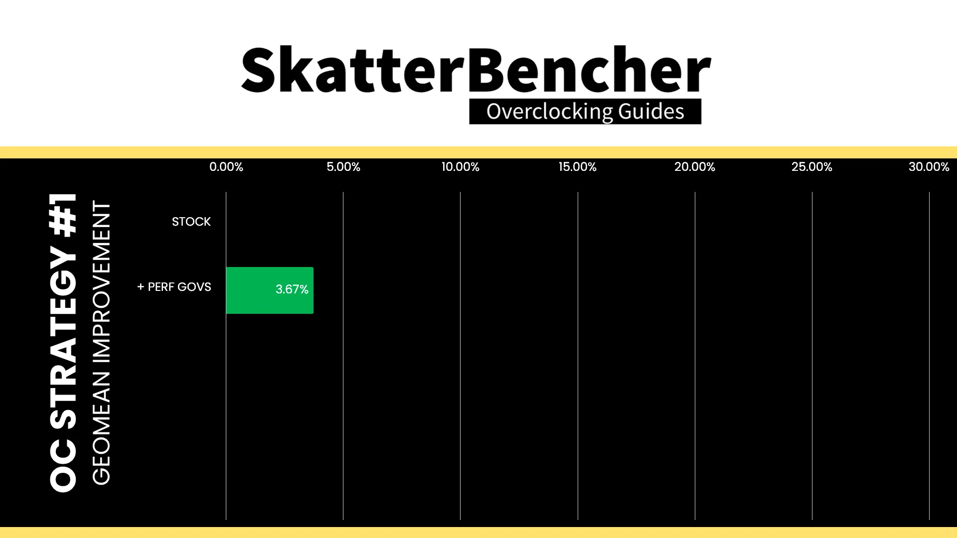
While we’re not exactly increasing the operating frequencies, adjusting the performance governors does have a decent impact on performance. Most notably, the memory and storage performance, which impacts GPU render workloads. The Geomean performance improvement is +3.67%, and we get a maximum improvement of +35.92% in GLMark2-ES2.
When running the S-TUI Stability Test, the average A55 Cluster clock is 1771 MHz with 0.950 volts, the average A76 Cluster0 clock is 2206 MHz with 1.000 volts, and the average A76 Cluster1 clock is 2250 MHz with 1.000 volts. The average SoC temperature is 38.6 degrees Celsius. The approximate wall power consumption is 12 watts.
OC Strategy #2: LPDDR5-6400
In our second overclocking strategy, we’re optimizing the memory subsystem by increasing the memory frequency to LPDDR5-6400.
Dynamic Memory Interface (DMC) Configuration
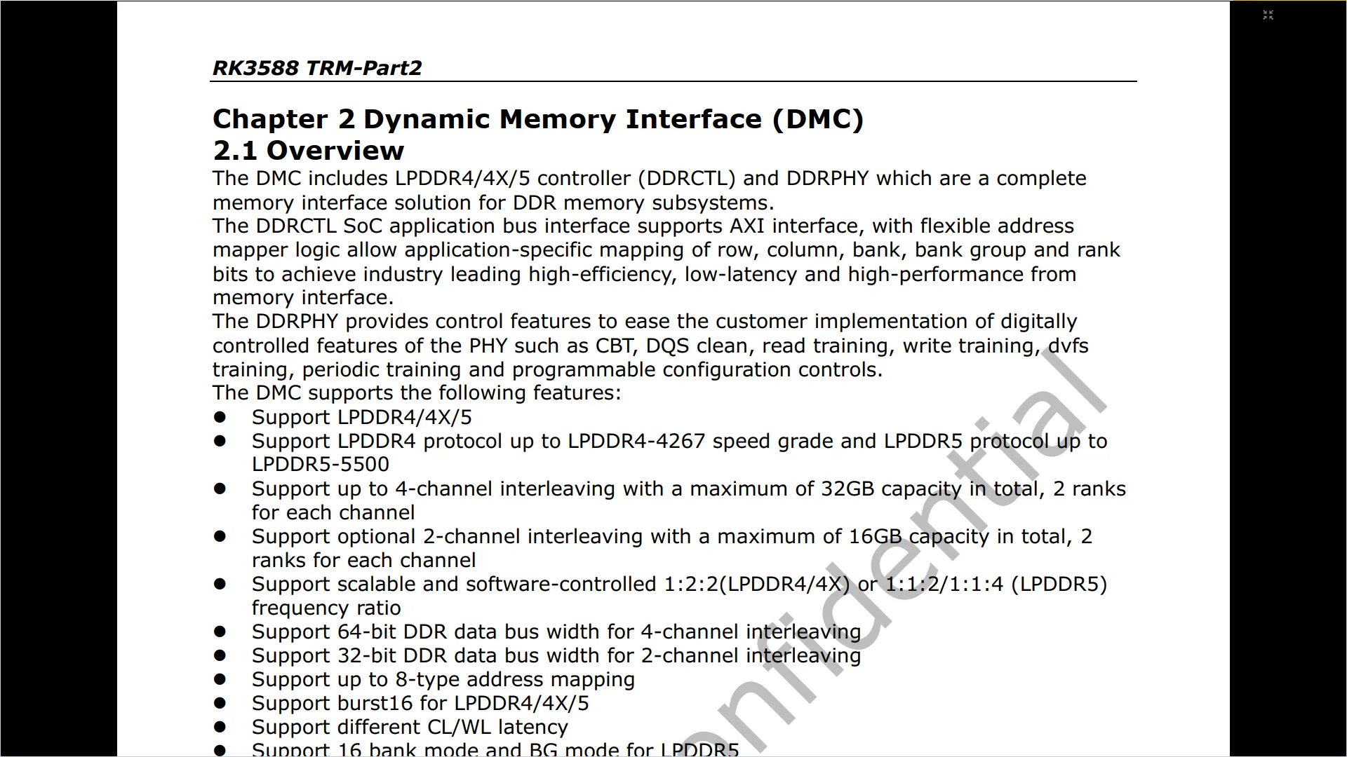
The Dynamic Memory Interface, or DMC, of the Rockchip RK3588 provides a complete memory interface solution with support for LPDDR4, 4X, and 5. There’s official support up to LPDDR4-4267 and LPDDR5-5500, and up to 32GB of system memory. It further supports a wide range of configuration parameters, such as multiple timing sets, most of which are set at boot.
The last part is crucial for overclocking efforts, as the memory configuration is provided by Rockchip as a binary blob, which we’re not able to fully change. Based on the DDR binary blob, the DMC governor builds an Operating Performance Point (OPP) table similar to how it works for the CPU cores. We can check the table using the same command from before:
- sudo cat /sys/kernel/debug/opp/opp_summary
In my case, it seems the available memory frequency options are:
- 534 MHz at 725 mV,
- 1320 MHz at 800 mV, and
- 1968 MHz at 875 mV.
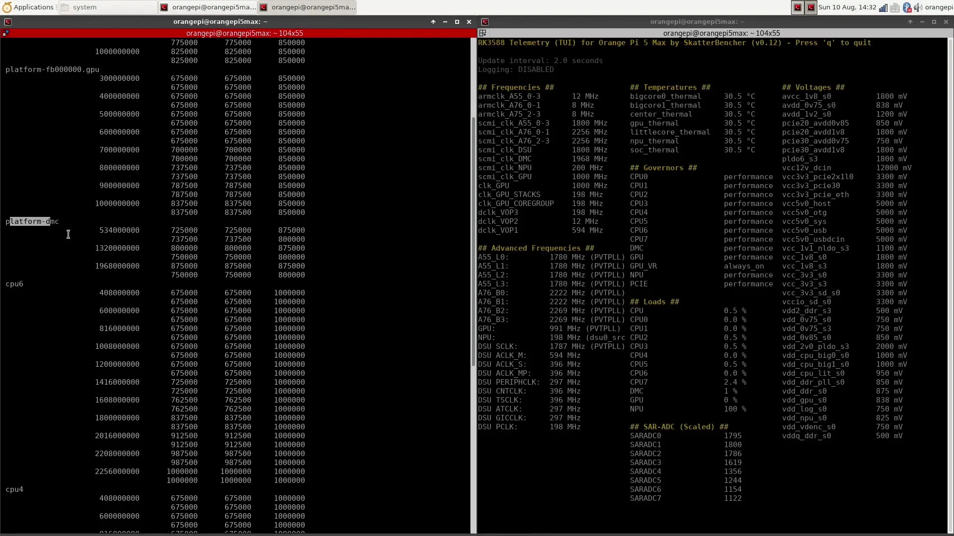
Again, the maximum frequency can differ between RK3588 boards.
Now, Rockchip provides a “ddrbin” tool that enables limited configuration of the memory via their GitHub page. You can refer to the ddrbin_tool_user_guide.txt document for more information. Fortunately, Boogiepop or hbiyik shared another useful tool called “rkddr,” which provides a simple user interface to make the adjustment.
There are two steps to the tuning process:
- Add a DMC OPP that supports the higher frequency
- Update the memory configuration using ddrbin or rkddr
Adding a DMC Operating Performance Point
Adding an OPP is not that complicated, but it’s still good to have a thorough understanding of how everything works. So, I’ll walk you through the entire process step by step.
Locating the Device Tree Binary (DTB)
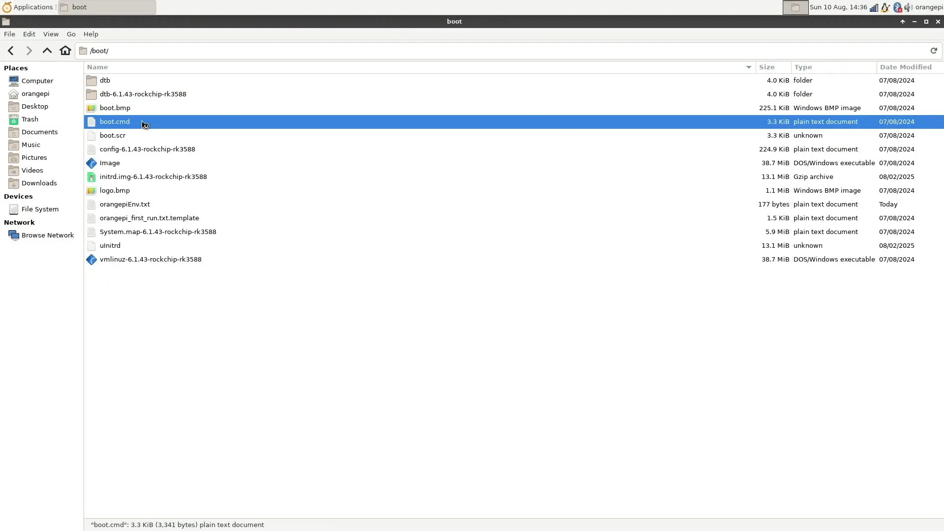
First, we must understand how the OPP table is built. For that, we need to find the device tree binary (DTB). The DTB is a data file that describes the hardware to the Linux kernel. This file is used early in the boot-up process and, therefore, is located in the /boot/ directory.
For the Orange Pi 5 Max, we first check the boot.cmd file to understand how the DTB is loaded at boot. Navigate to the /boot/ directory and open /boot/boot.cmd.
Here, we find two important lines:
- load ${devtype} ${devnum} ${load_addr} ${prefix}orangepiEnv.txt
- load ${devtype} ${devnum} ${fdt_addr_r} ${prefix}dtb/${fdtfile}
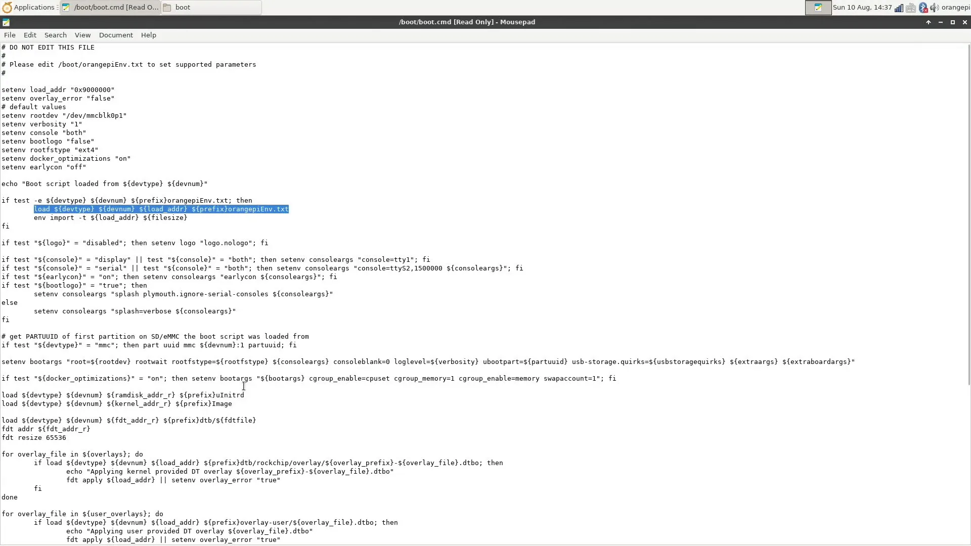
The first line tells us there’s a text file called orangepiEnv.txt, which contains some configurable parameters. The second line tells us the parameter fdtfile is used to pinpoint the DTB file.
Now, we can check the /boot/orangepiEnv.txt document to find the relevant DTB information.
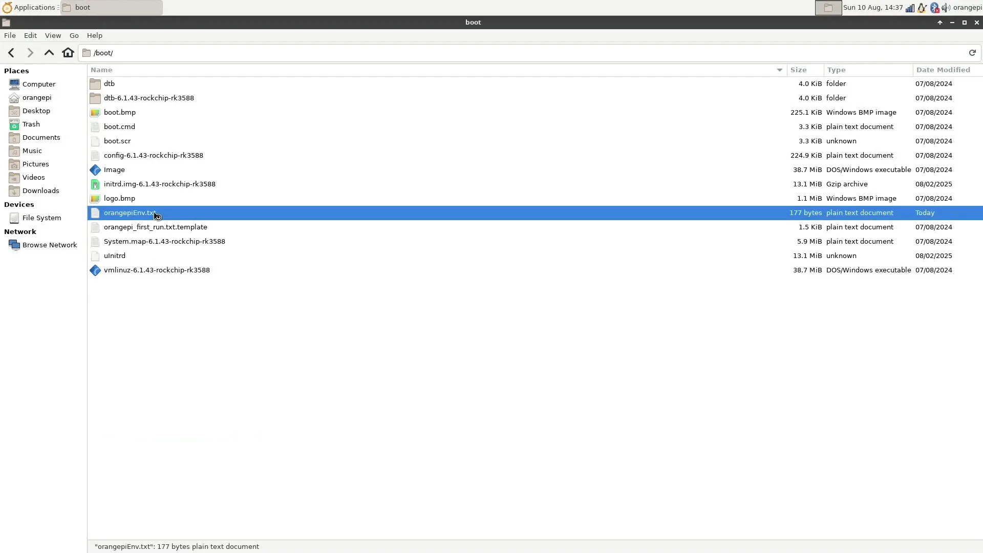
You’ll find a line that says:
- fdtfile=/rockchip/rk3588-orangepi-5-max.dtb
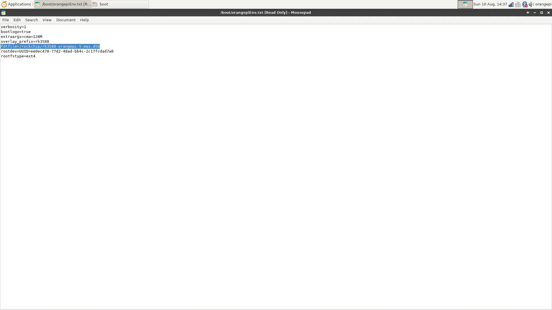
So, let’s now check the files in the folder /boot/dtb/rockchip. Here we can find several device trees for various Orange Pi 5 devices, including the one for our Orange Pi 5 Max: rk3588-orangepi-5-max.dtb.
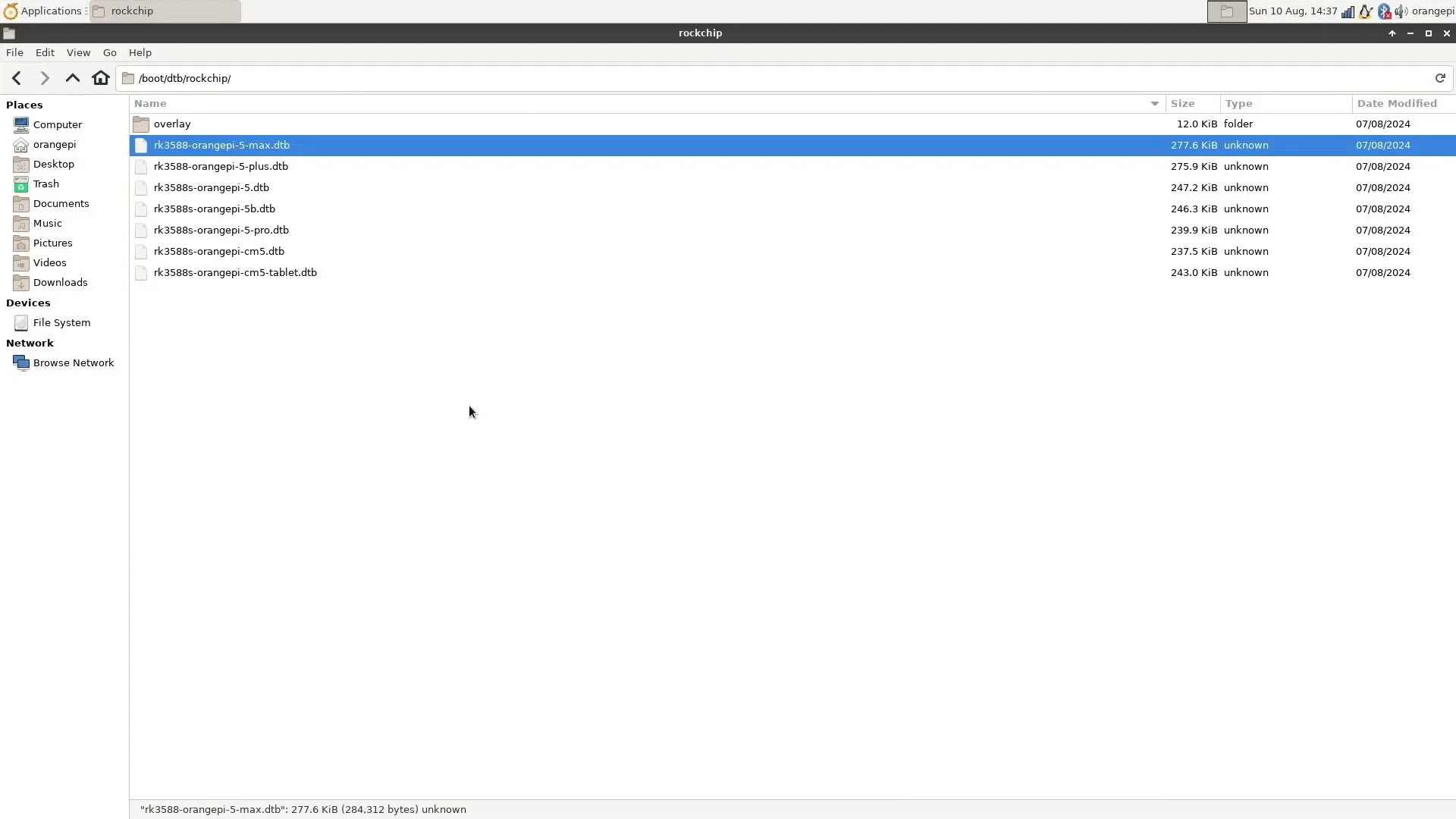
Decompiling the Device Tree Binary (DTB)
The DTB file is a binary file, which means we can’t directly read its contents. It’s pretty easy to convert the binary DTB into a readable Device Tree Source (DTS) file with the Device Tree Compiler tool using the following command:
- dtc -I dtb -O dts -o rk3588-orangepi-5-max.dts rk3588-orangepi-5-max.dtb
Where,
- DTC means device tree compiler
- -I is the input filetype
- -O is the output filetype
- -o is the output filename
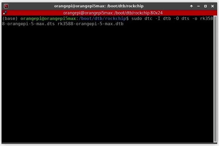
The output is a DTS file, which we can now open using any text editing software.
Reading the Device Tree Source (DTS)
The DTS file contains all the information about our hardware – or at least, that’s the idea. For development boards, the device tree is often incomplete or inaccurate and requires help from the open source community to get patched.
Also note that the device tree configuration can differ between Linux kernels. For example, in the latest stable Linux kernel, you’ll find that the device tree for the Orange Pi 5 is split up into multiple trees using #includes. So don’t just blindly copy any modification we make to our device tree. Make sure the modifications are appropriate for your specific device and kernel.
For this overclocking strategy, we’re interested in the DMC configuration. We find two relevant data structures: “dmc” and “dmc-opp-table”. The most interesting lines of the DMC structure are:
- Operating-points-v2, which tells us there’s an opp table linked to the DMC
- Center-supply, which tells us what voltage regulator is powering the DMC
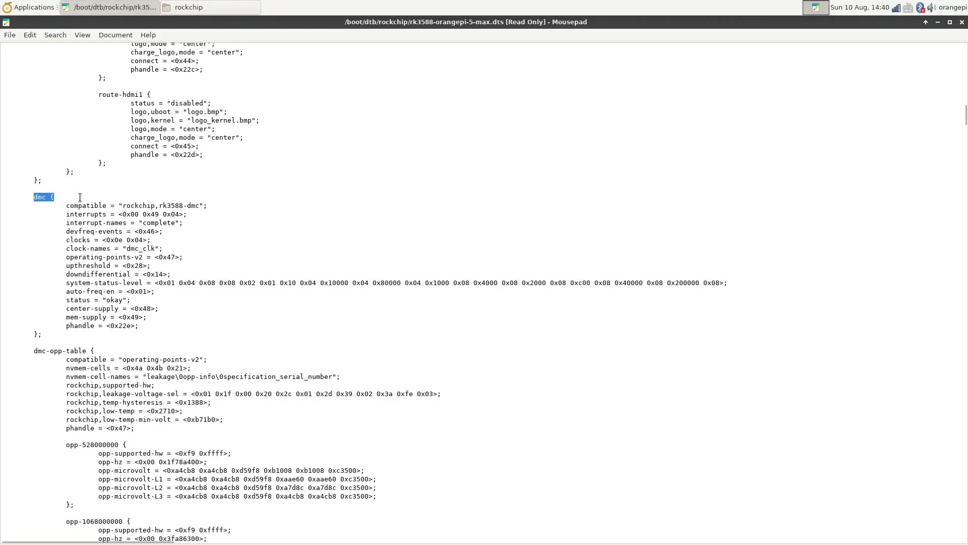
The hex code in brackets provides a reference to the “phandle” or pointer that defines the node. In our case, operating-points-v2 links to 0x47 and center-supply links to 0x48. A quick search for those handles tells us that:
- Operating-points-v2 links to the dmc-opp-table, and
- Center-supply links to the vdd_ddr_s0 voltage supply.
Let’s have a closer look at the dmc-opp-table, where we find multiple OPP nodes. You can learn about the various parameters from the kernel.org documentation.
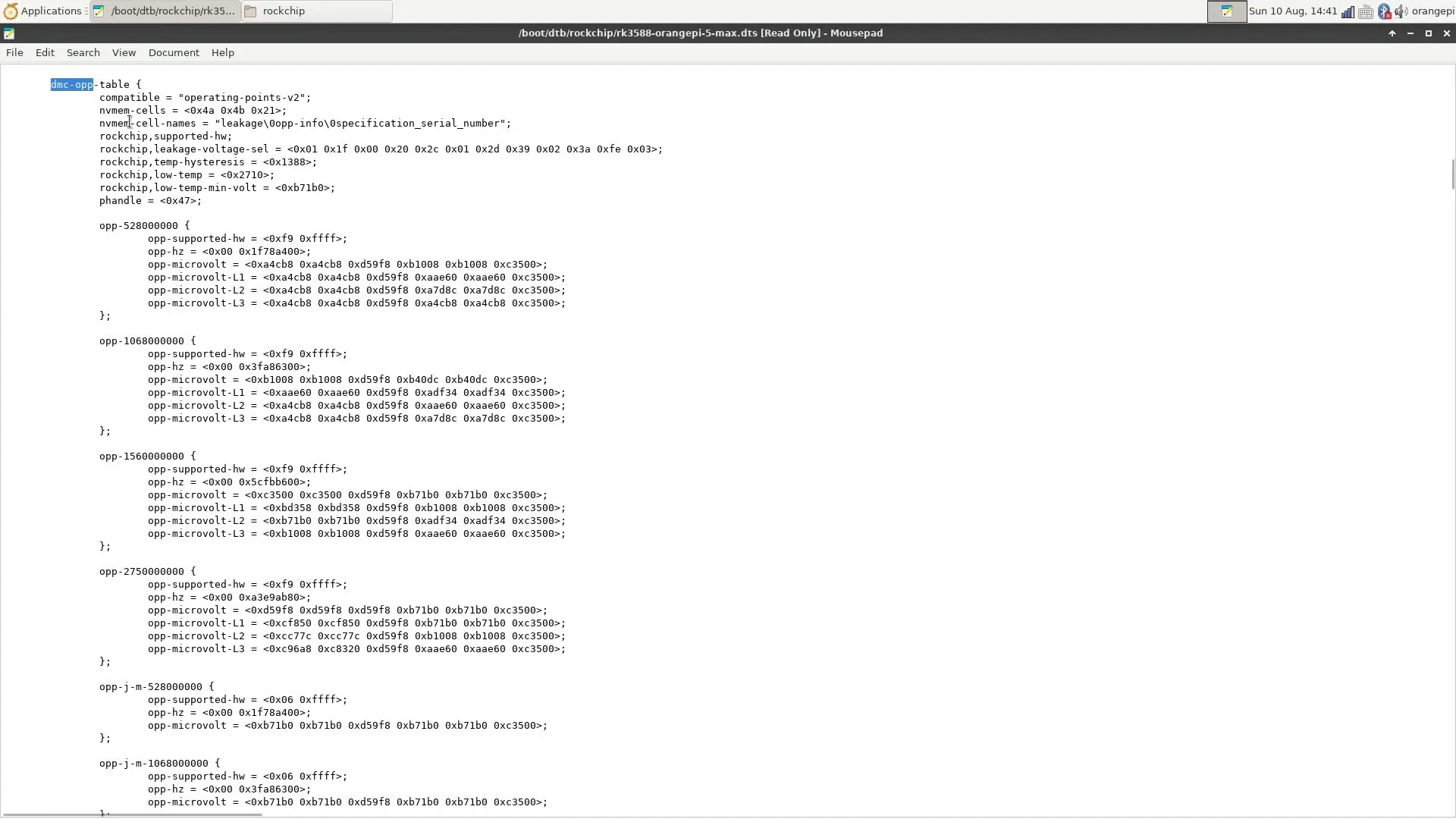
The long story short is that each node defines an operating point by a number of parameters, including but not limited to voltage, frequency, and current.
Modifying the Device Tree
There are two ways to modify the DTB: either modify the Device Tree Source (DTS) and recompile the Device Tree Binary (DTB), or create a Device Tree Binary Overlay (DTBO). There are situations where you must recompile the DTB, but it’s usually easier to simply work with a DTBO. For the purpose of this guide, I’ll show both options.
Option 1: Recompiling the DTB
To add a performance point for our target frequency of LPDDR5-6400, we can either add a new OPP or modify an existing one. You’ll find that our device tree already has a higher OPP than the frequency we’re running at: 2750 MHz instead of 1968 MHz.
So, we can copy the entire opp-2750000000 structure and paste it right below. Then, we change the following values:
- Name: opp-2750000000 -> opp-3200000000
- Frequency: opp-hz = <0x00 0xa3e9ab80> -> opp-hz = <0x00 0xbebc2000>
Let’s save this as a new DTS called rk3588-orangepi-5-max-3200.dts
Now we can recompile the DTS into a DTB using the following command:
- dtc -I dts -O dtb -o rk3588-orangepi-5-max-3200.dtb rk3588-orangepi-5-max-3200.dtb
Next, we can place the new DTB file into the /boot/dtb/rockchip/ directory.
- sudo cp rk3588-orangepi-5-max-3200.dtb /boot/dtb/rockchip
And, lastly, update the DTB line in the /boot/orangepiEnv.txt text file.
- sudo nano /boot/orangepiEnv.txt
To keep track of changes, I prefer to comment out the original line and add a new line with the modified device tree.
Save the file and reboot. After the reboot you’ll find that the frequency increased but not to the 3200 MHz we intended. We’ll address that in just a minute.
Option 2: Creating a DTBO
To create a new performance point using a device tree overlay is pretty simple. Simply create a text file called rk3588_dmc3200.dts with the following content:
/dts-v1/;
/plugin/;

/ {
    fragment@0 {
        target = <&dmc_opp_table>;
        __overlay__ {
            opp-3200000000 {
        		opp-supported-hw = <0xf9 0xffff>;
        		opp-hz = <0x00 0xbebc2000>;
        		opp-microvolt = <0xd59f8 0xd59f8 0xd59f8 0xb71b0 0xb71b0 0xc3500>;
        		opp-microvolt-L1 = <0xcf850 0xcf850 0xd59f8 0xb71b0 0xb71b0 0xc3500>;
        		opp-microvolt-L2 = <0xcc77c 0xcc77c 0xd59f8 0xb1008 0xb1008 0xc3500>;
        		opp-microvolt-L3 = <0xc96a8 0xc8320 0xd59f8 0xaae60 0xaae60 0xc3500>;
                } ;
            };
    };
};
You’ll find that the content is the same as a regular DTS file, but shorter. With an overlay file, we’re simply referencing a specific device node and adding a new OPP entry.
Now we can recompile the DTS into a DTBO using the following command:
- dtc -I dts -O dtb -o rk3588_dmc3200.dtbo rk3588_dmc3200.dts
You can see, the command is almost identical to the one for compiling a DTS into a DTB, except for the file type extension of the output file.
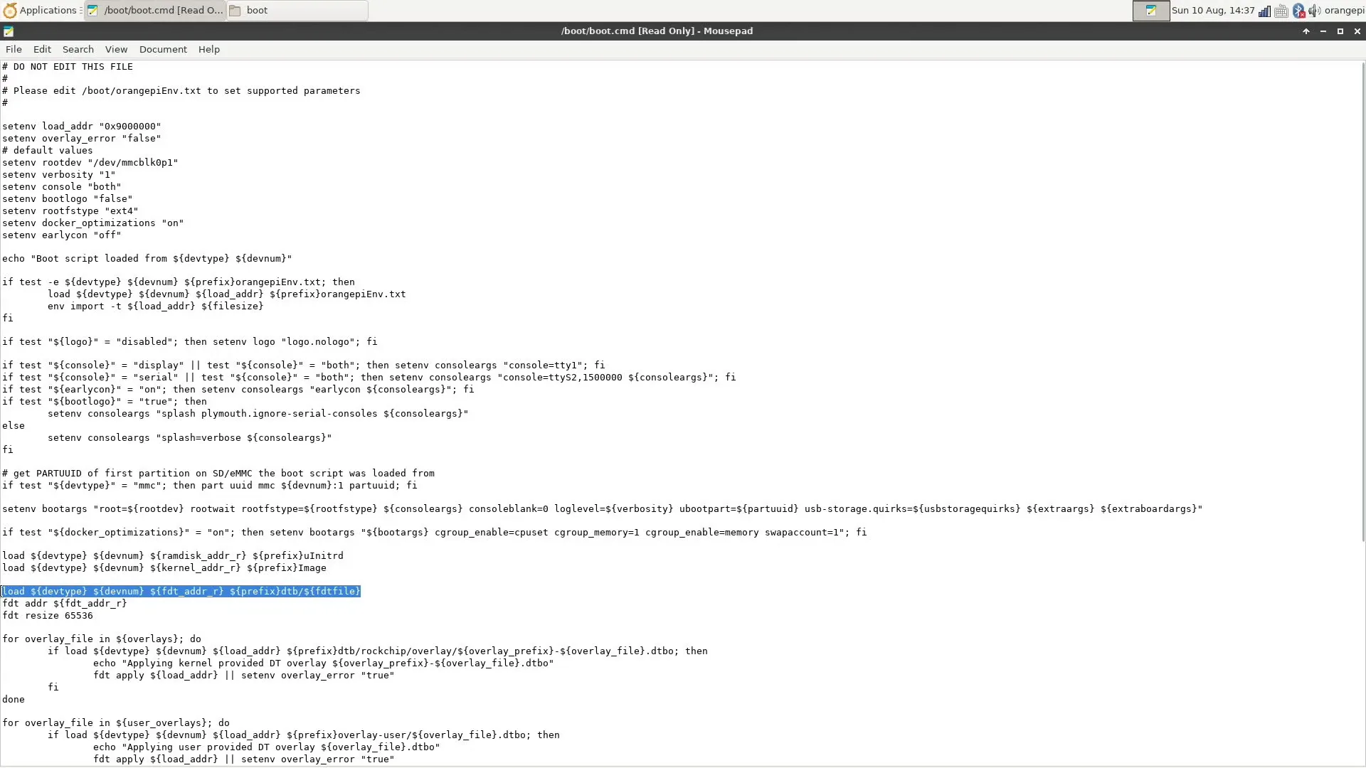
Now, we need to place the DTBO file in the right folder. To figure out which folder, we can check the /boot/boot.cmd file again.
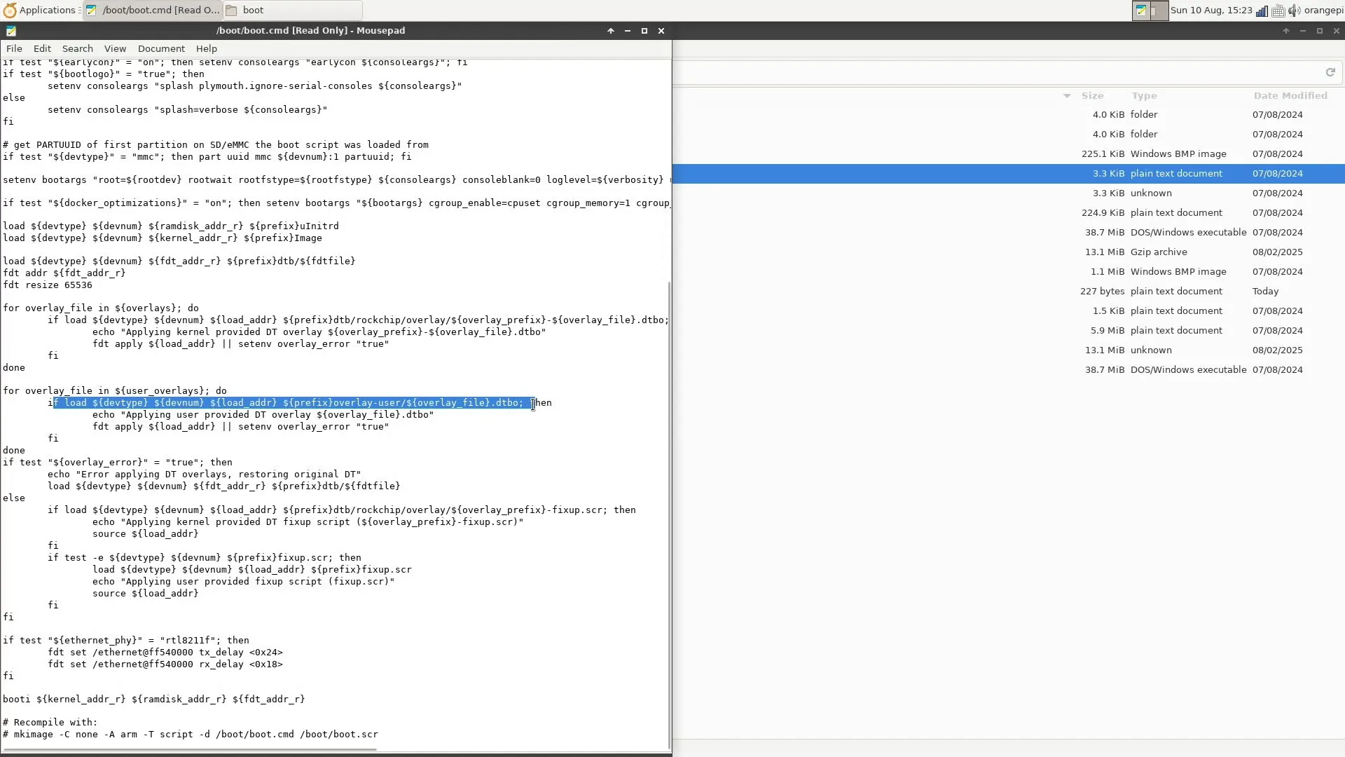
This is the relevant line:
- for overlay_file in ${user_overlays}; do
if load ${devtype} ${devnum} ${load_addr} ${prefix}overlay-user/${overlay_file}.dtbo;
The first line tells us there’s a parameter called {user_overlays} which lists user-made overlays to be used at boot. The second line tells us the overlay files should be saved in the /boot/overlay-user/ directory.
First, check if the directory exists and, if not, add the directory. Simply open the terminal in /boot/, then type.
- sudo mkdir overlay-user
Next, go back to the folder where you saved the DTBO file. Open the terminal again and copy the dtbo into the newly created overlay-user directory.
- sudo cp rk3588_dmc3200.dtbo /boot/overlay-user
Next, open the /boot/orangepiEnv.txt text file and add the following line:
- sudo nano /boot/orangepiEnv.txt
- user_overlays=rk3588_dmc3200
Make sure to activate the fdtfile line of the original DTB since that’s what the DTBO references.
Save the file and reboot. After the reboot, again, you’ll find that the frequency increased but not to the 3200 MHz we intended, but 2400 MHz instead. We’ll address that in just a minute.
Updating the DDR Binary Blob
The final step of this overclocking strategy is to enable the higher memory frequency. As I mentioned before, there are two ways to do it: the hard way using Rockchip’s ddrbin tool or the easy way using boogiepop’s rkddr tool. Let’s do it the easy way.
First, clone the GitHub to your drive
- git clone https://github.com/hbiyik/rkddr.git
Then open the script
- sudo ./rkddr/rkddr
Browse to [lp5] and set the first line to 3200. Then exit the application and confirm the settings with “y”.
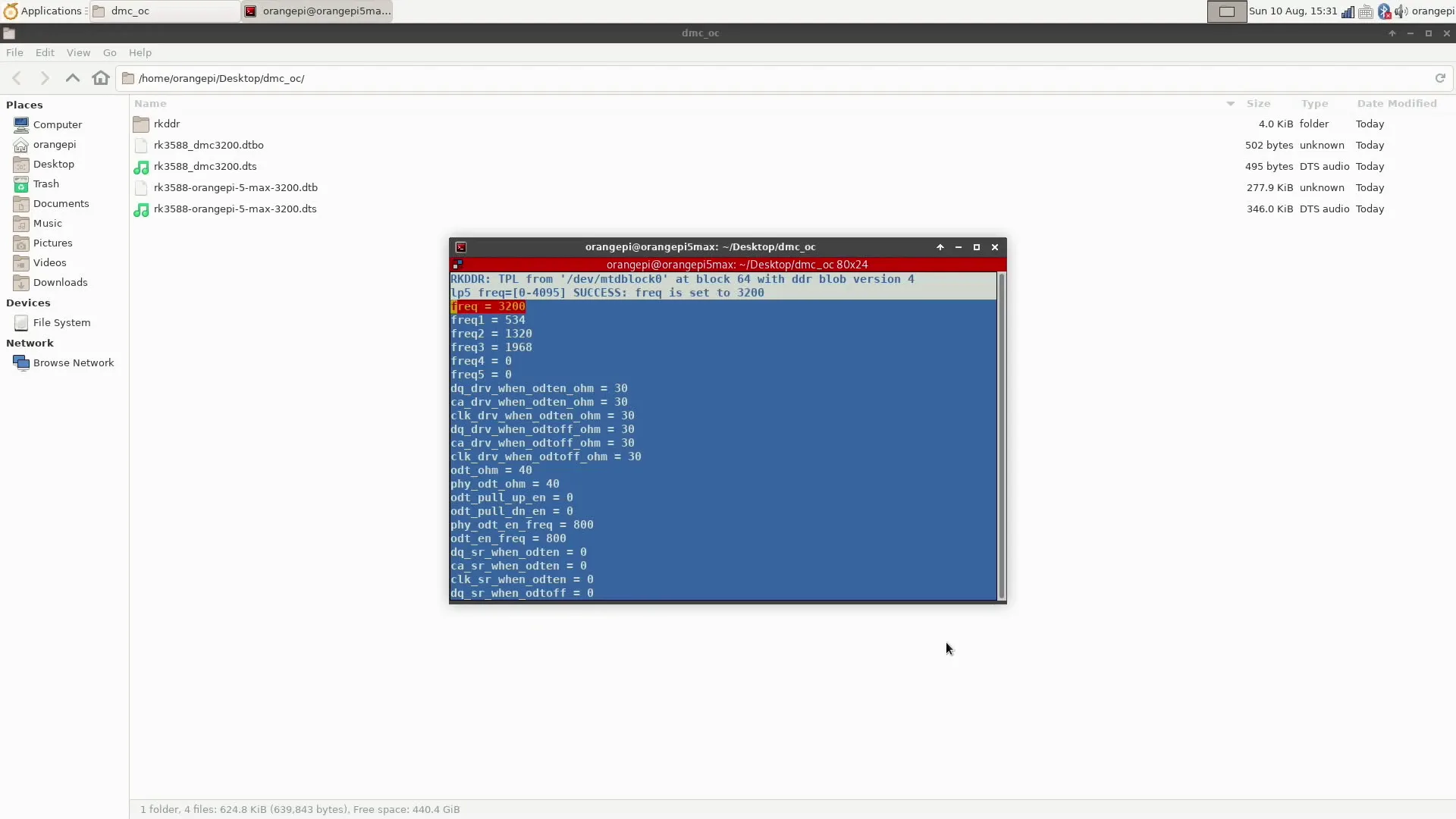
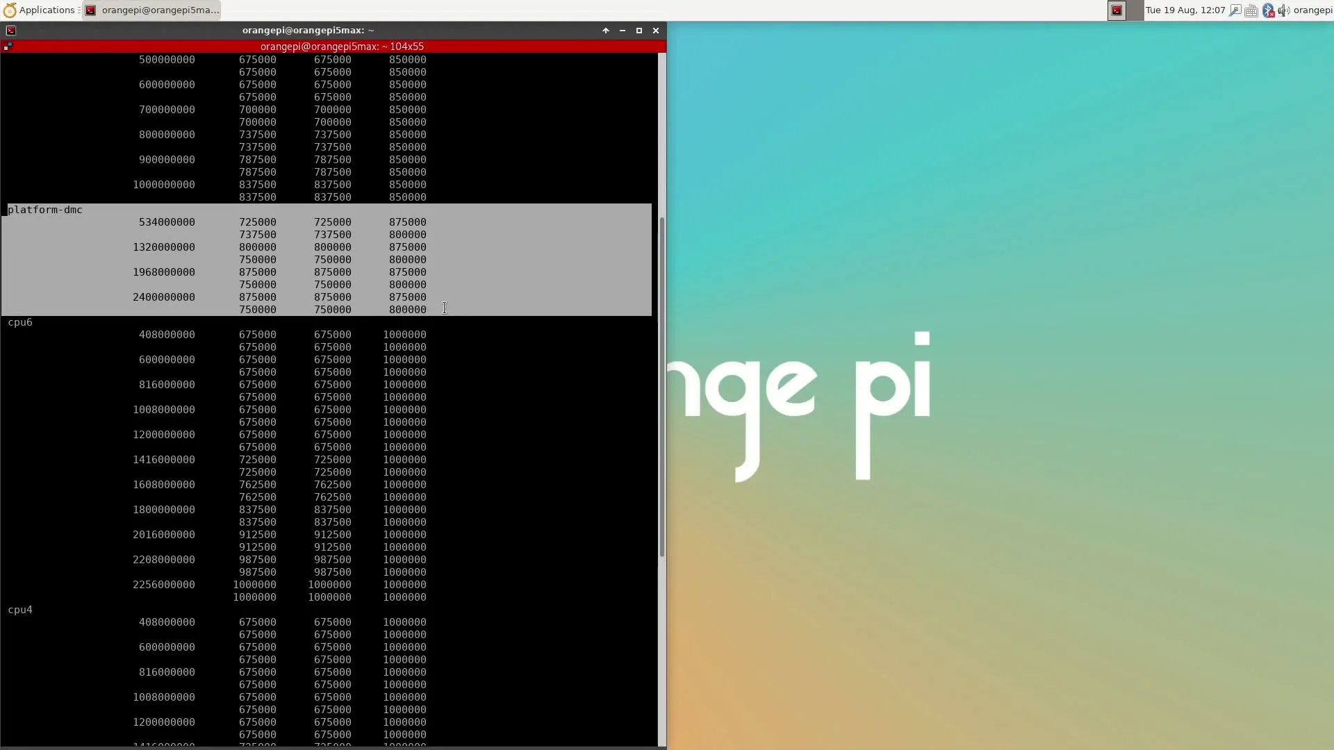
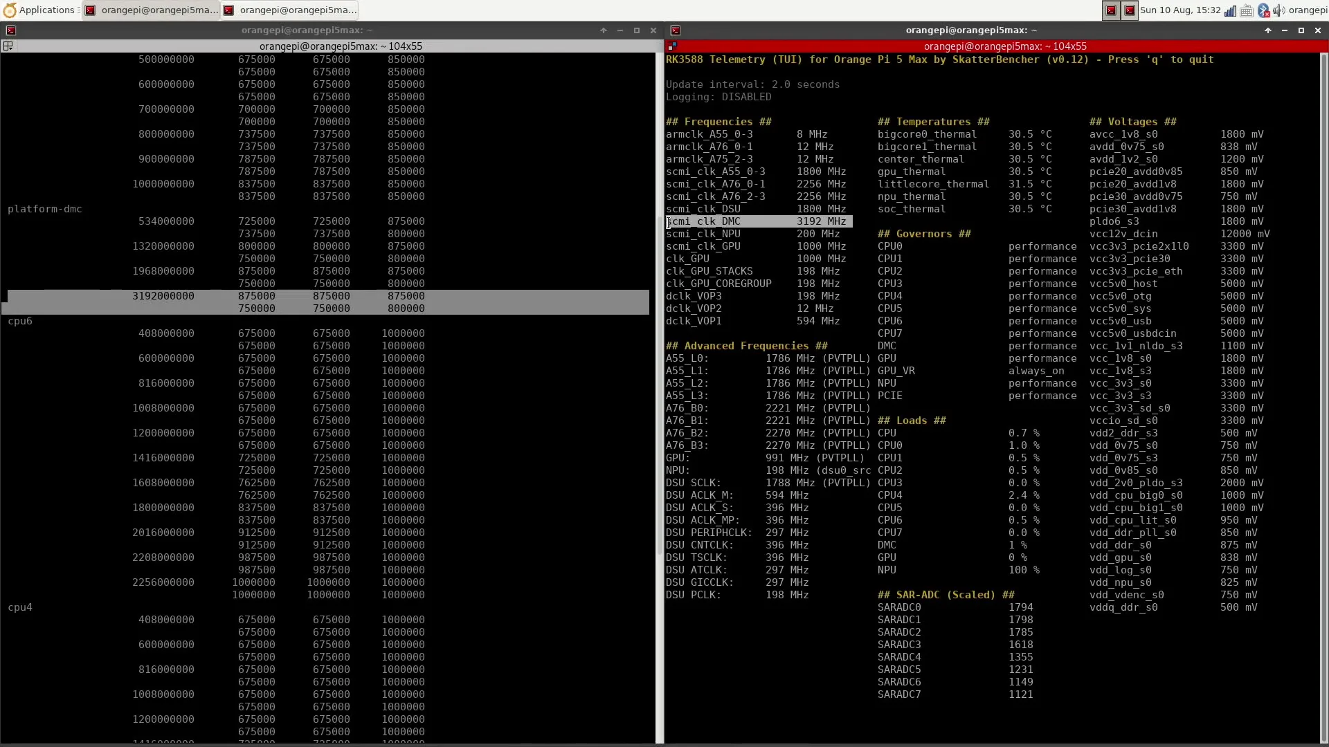
Now reboot the system. After the reboot, you can check the clock summary or my telemetry tool to verify DMC is now running at 3192 MHz.
Benchmark Results
We rerun the benchmarks and check the performance increase compared to the default operation.
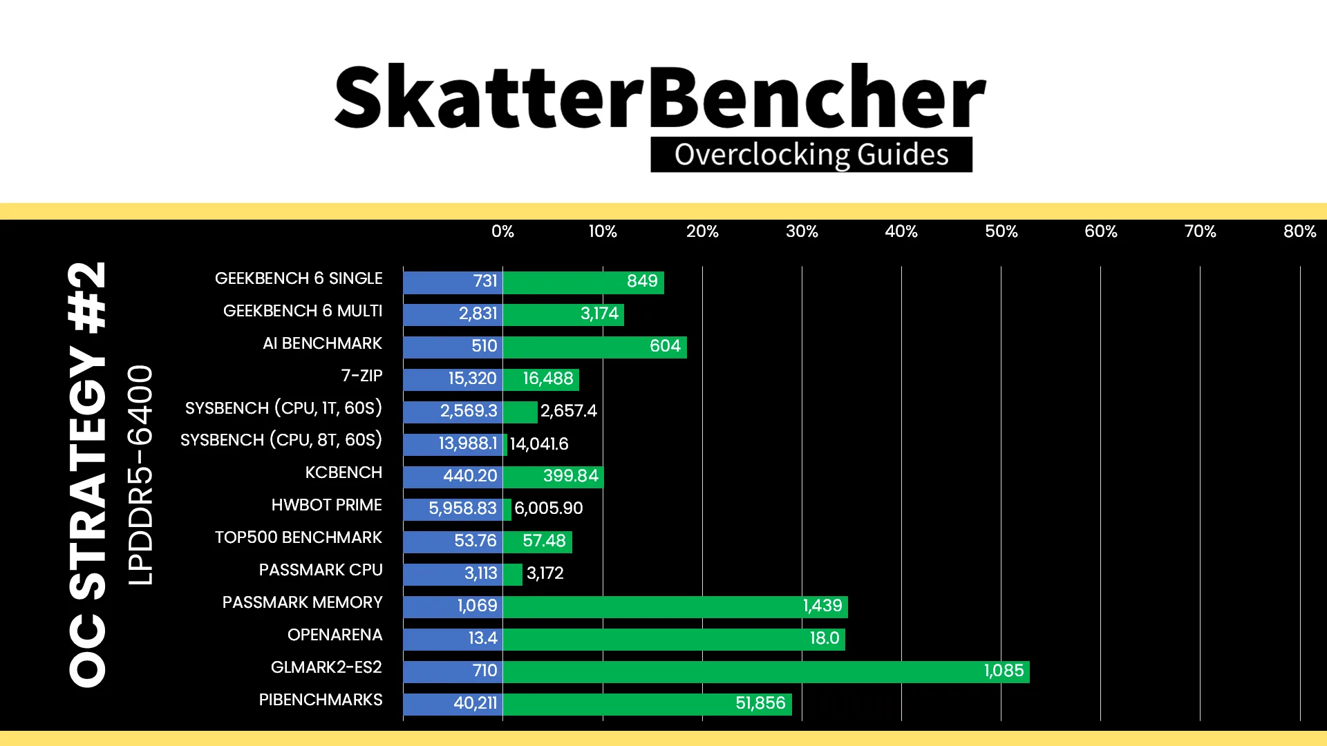
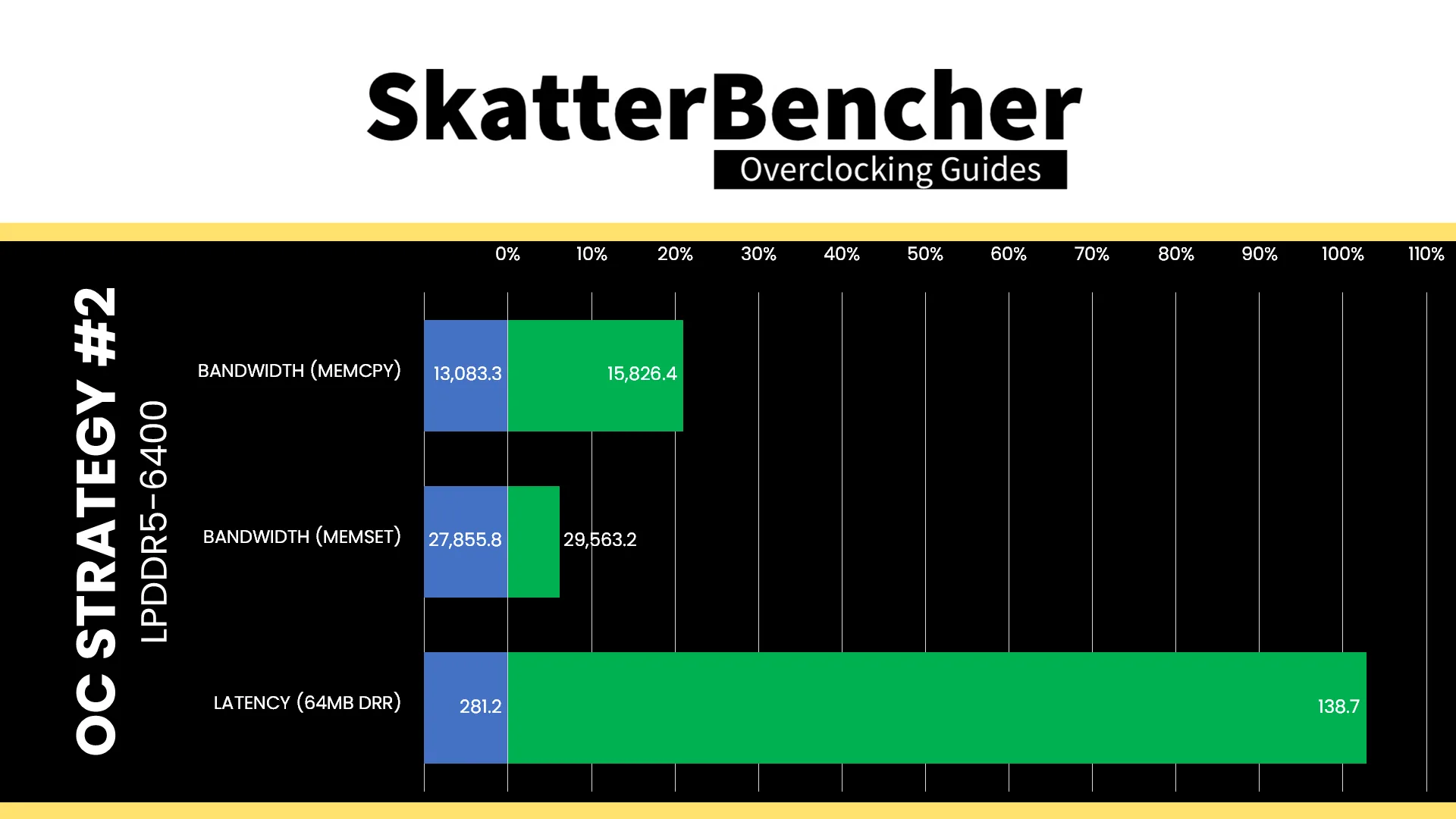
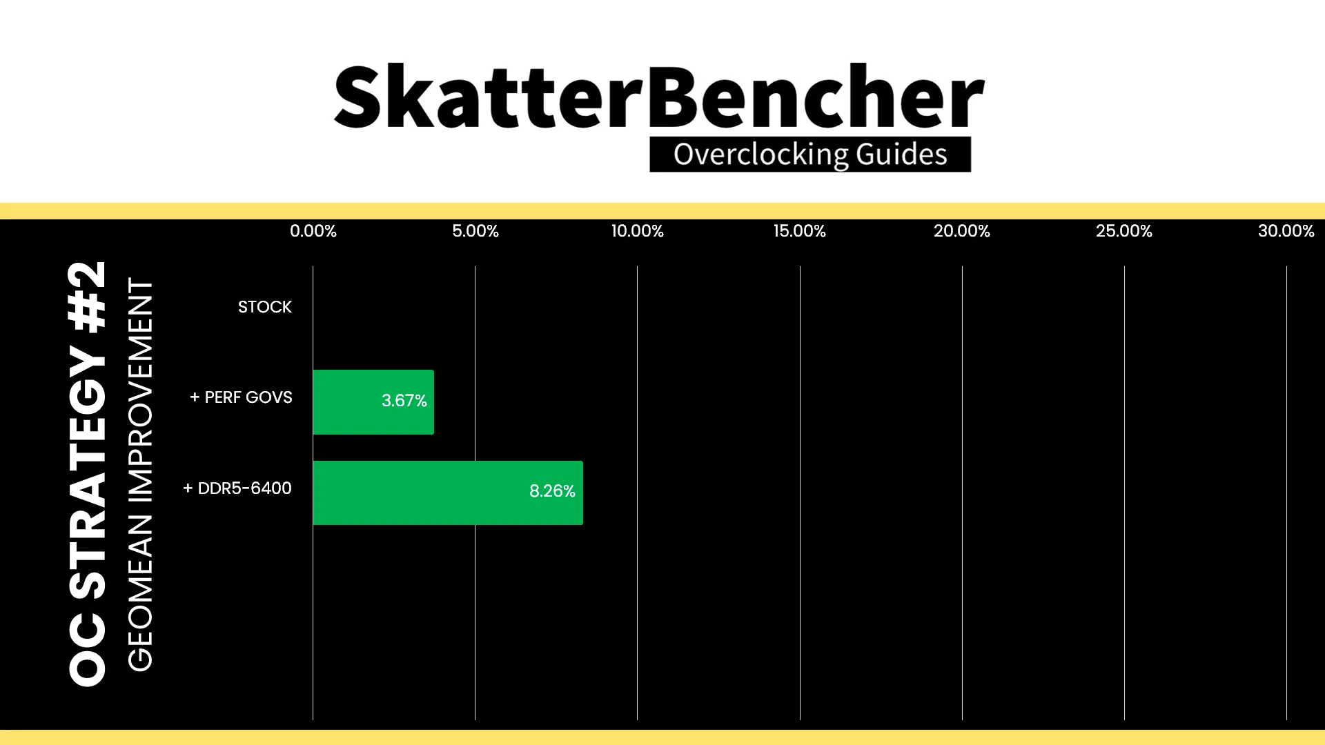
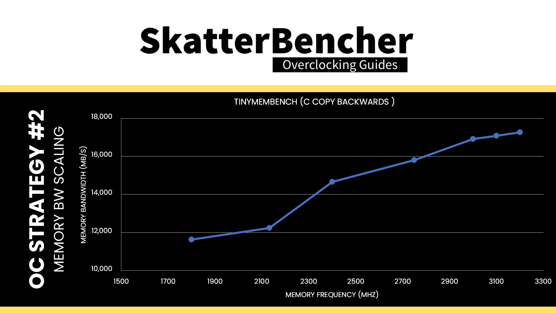
Similar to our X86 overclocking adventures, increasing memory performance helps improve performance in memory-sensitive workloads. The performance of the integrated Mali-G610 graphics also improves noticeably. Looking at the memory performance, adjusting the memory frequency specifically improves the latency. The Geomean performance improvement is +8.26%, and we get a maximum improvement of +52.82% in GLMark2-ES2.
Here’s the memory bandwidth scaling with various DMC frequencies.
When running the S-TUI Stability Test, the average A55 Cluster clock is 1771 MHz with 0.950 volts, the average A76 Cluster0 clock is 2206 MHz with 1.000 volts, and the average A76 Cluster1 clock is 2249 MHz with 1.000 volts. The average SoC temperature is 38.7 degrees Celsius. The approximate wall power consumption is 12 watts.
OC Strategy #3: PVTPLL Overvolting
In the third overclocking strategy, we finally get to overclock the CPU cores. We do this by leveraging Rockchip’s PVTPLL technology, which requires overvolting to overclock. Let’s have a look.
Rockchip PVTPLL Technology
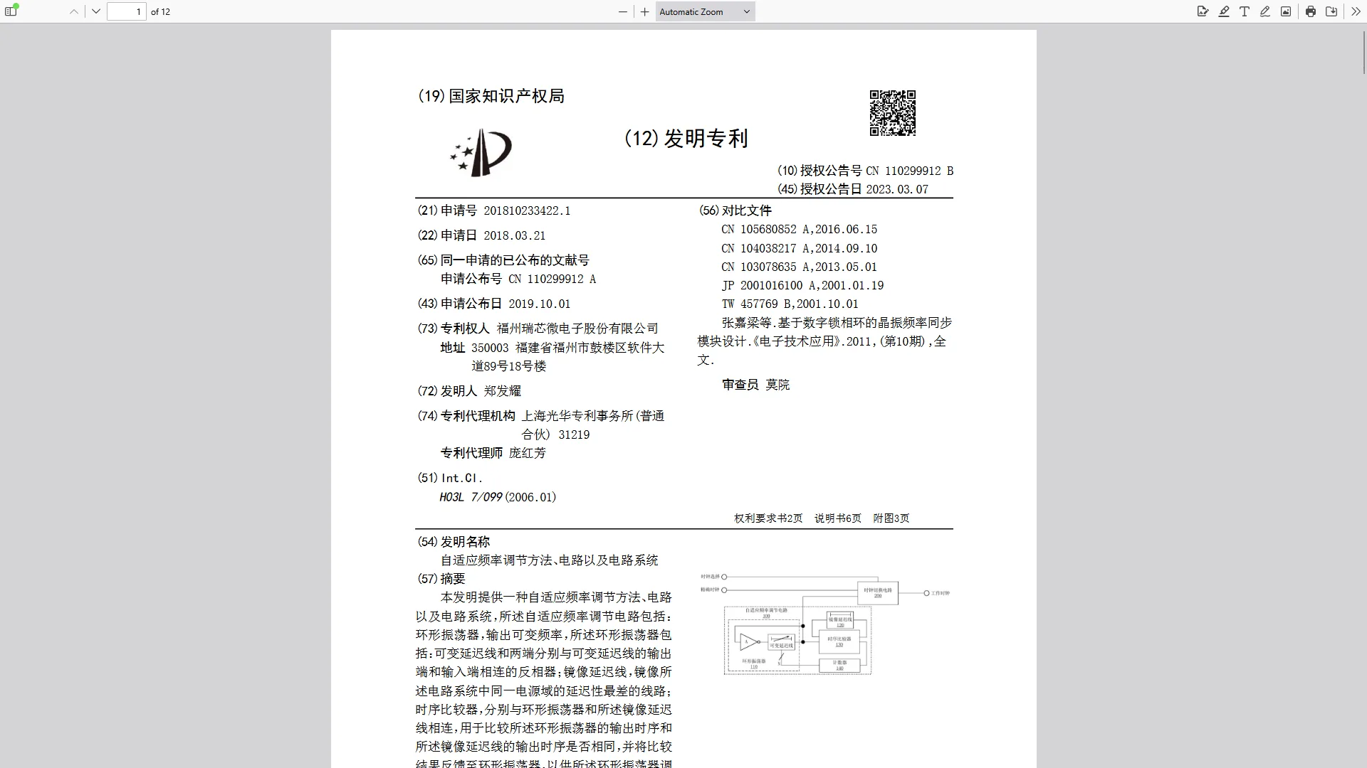
Rockchip filed a patent (CN110299912A) for its adaptive frequency technology on March 21, 2018. The patent describes a self-adaptive frequency tuning circuit that dynamically adjusts frequency output in response to process, voltage, and temperature changes.
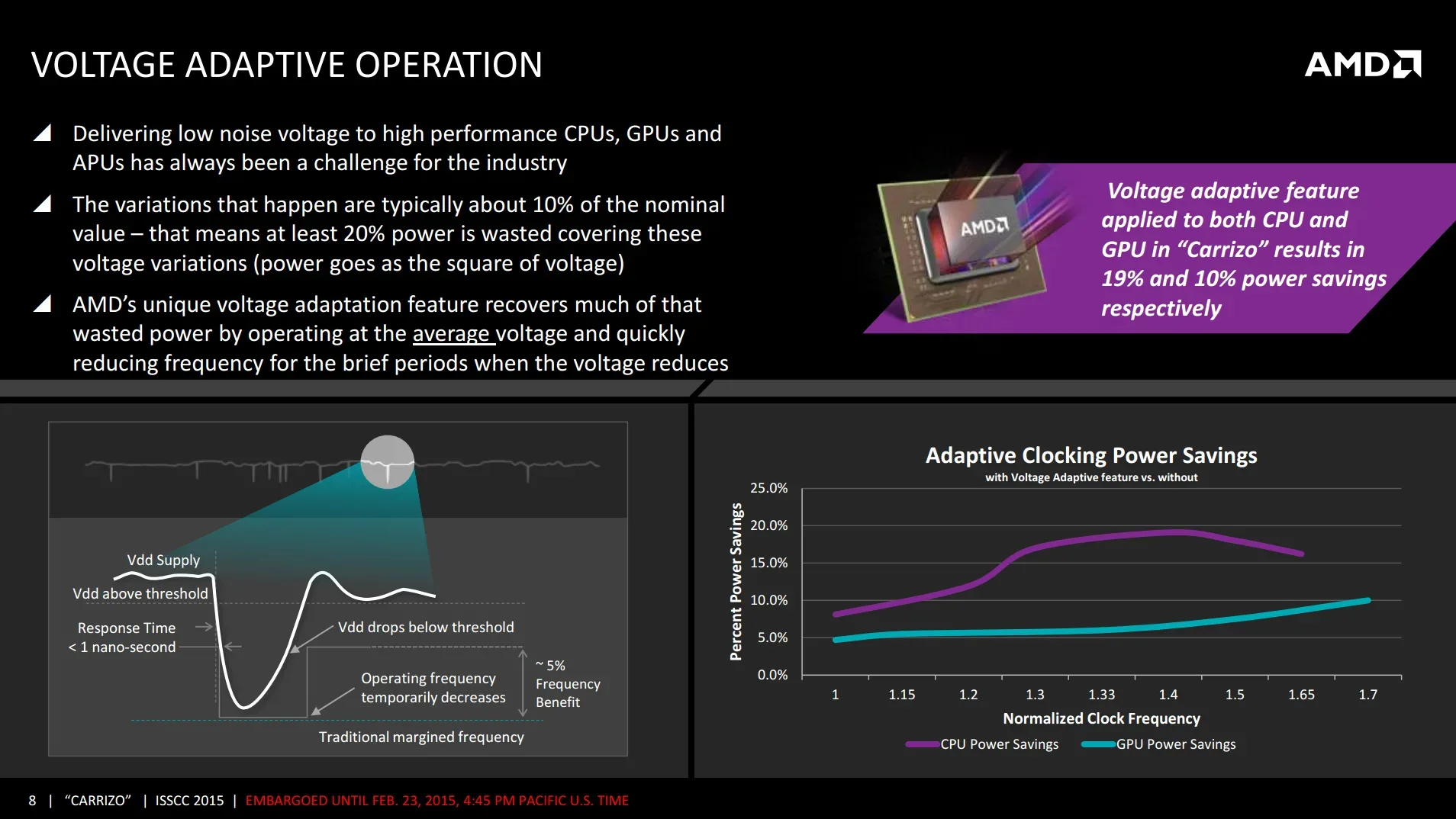
Experienced overclockers will immediately think of AMD’s Voltage Adaptive Operation technology, which also adapts the clock frequency to the operating voltage.
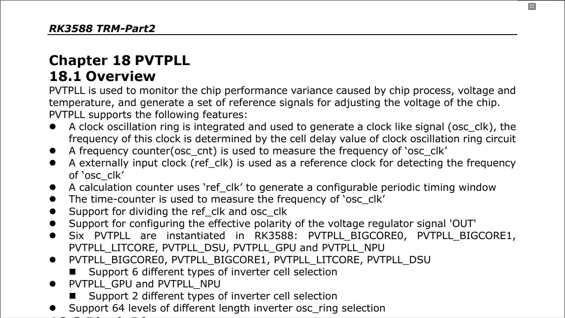
The RK3588 SoC supports six PVTPLLs for the following IP blocks:
- BigCore0 (2x Cortex-A76)
- BigCore1 (2x Cortex-A76)
- LittleCore (4x Cortex-A55)
- DynamIQ Shared Unit (DSU)
- GPU (Mali-G610)
- NPU
You can monitor the PVTPLL frequencies using my telemetry tool.
As I mentioned before, you’ll find that the actual operating frequency differs from the available operating performance points. In fact, turns out the actual operating frequency is determined only by the operating voltage and not the OPP-defined frequency … although it might seem so if we map the OPP and PVTPLL frequencies.
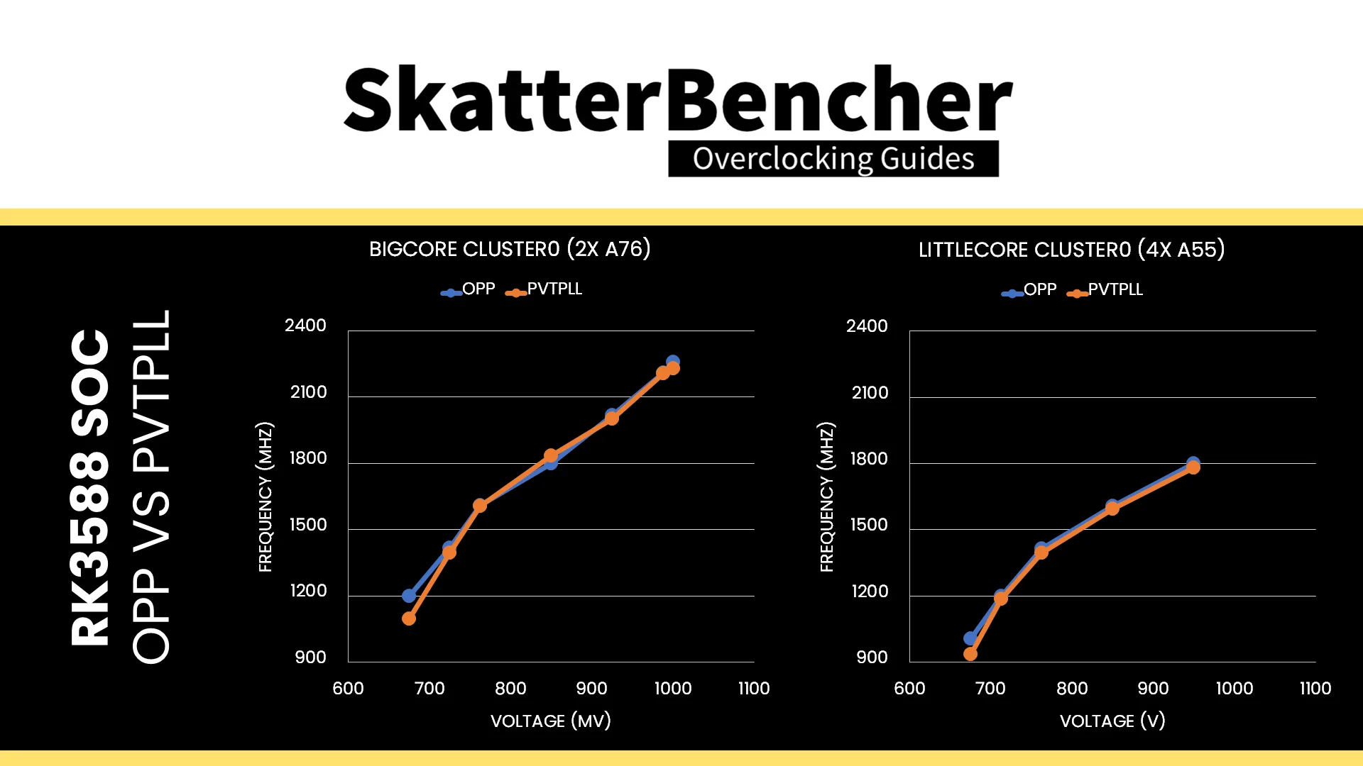
The easiest way to illustrate this is by creating an OPP table with just 2 points: 1200 MHz at 850 mV and 1800 (A55) / 2256 (A76) MHz at 900 mV. The expected behavior is that the CPU clusters would operate at 1200 and 1800/2256 MHz; however, the reality is that they work at totally different frequencies:
- 200-300 MHz higher at 850 mV
- 100-200 MHz lower at 900 mV
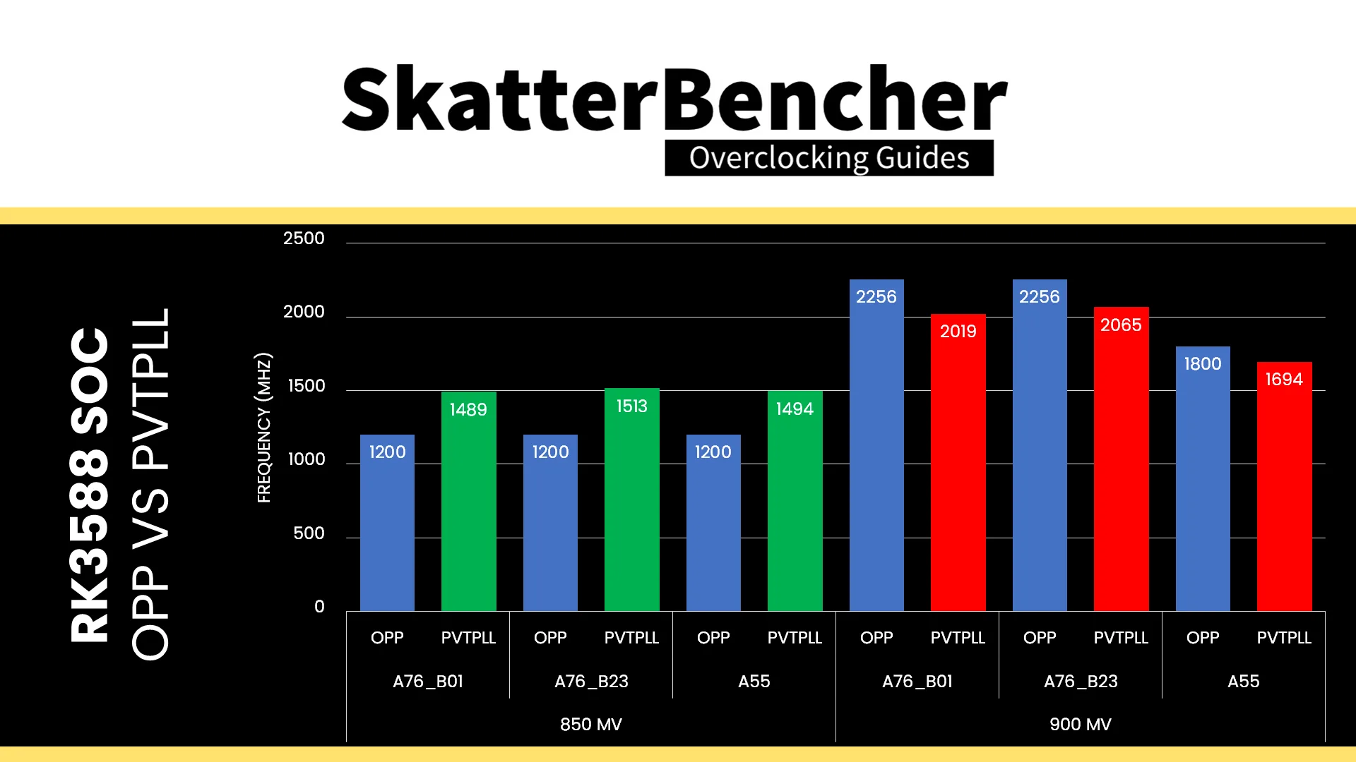
The bad news is that we can’t rely on the traditional overclocking method of adding OPPs to increase the clock frequency. However, the good news is that we now have a clear path on how to increase the operating frequency: overvoltage.
Before we start overvolting, let’s have a look at the Orange Pi 5 Max voltage topology.
Orange Pi 5 Max Voltage Topology
The Orange Pi 5 Max voltage topology consists of 1x RK806 PMIC and 2x RK860 step-down DC/DC voltage regulators. The PMIC takes care of the vast majority of the voltage regulation, whereas the DC/DC regulators specifically cater to the two Cortex-A76 clusters.
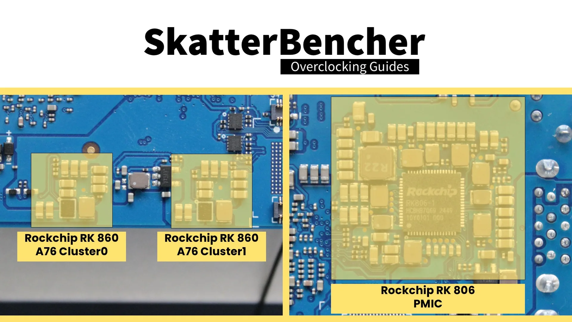
One RK860 VR provides the voltage for A76 Cluster0 (vdd_cpu_big0) and the NPU (vdd_npu), whereas the other provides the voltage only for A76 Cluster1 (vdd_cpu_big1).
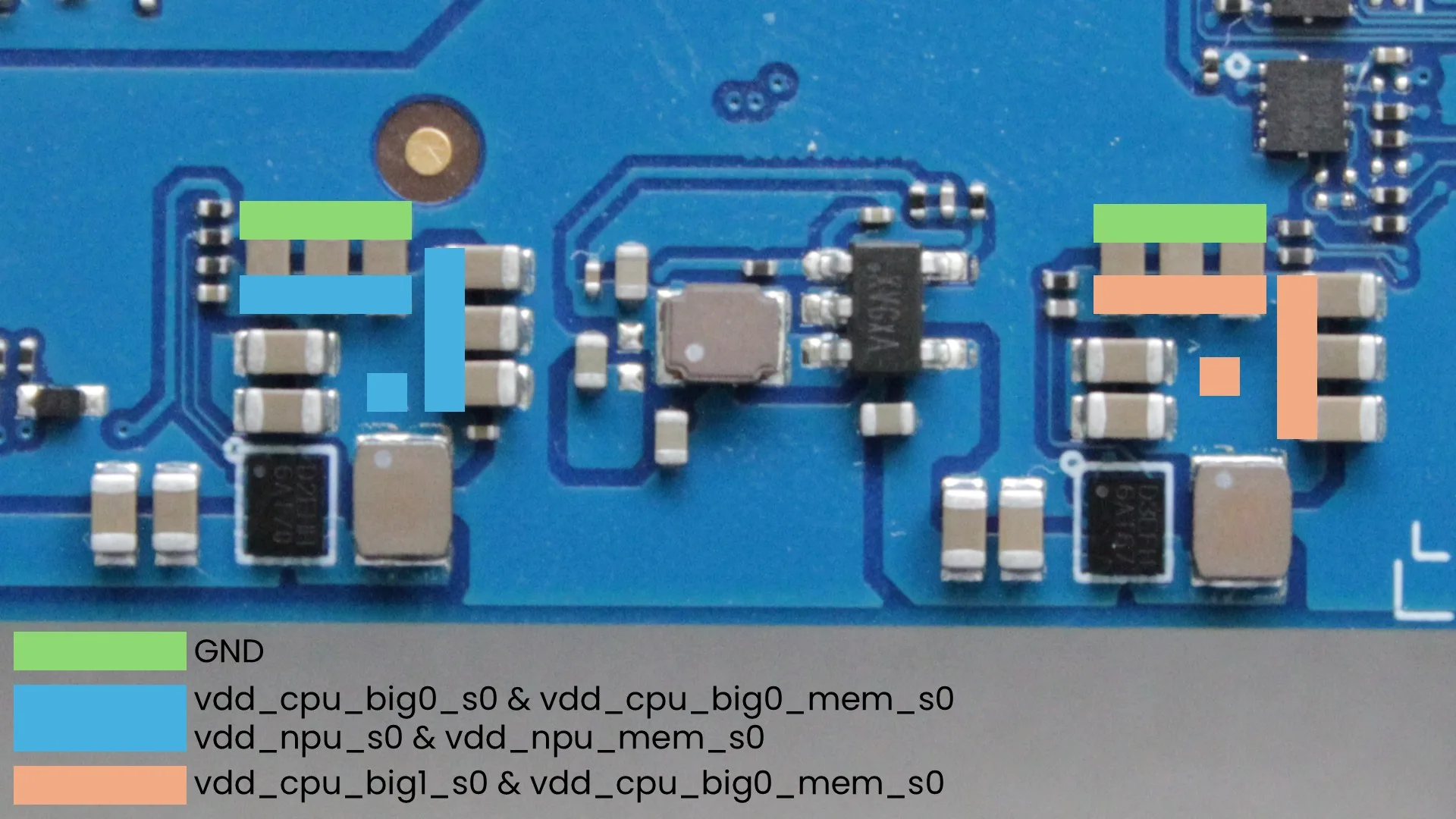
The RK806 PMIC provides power for 10 DC/DC buck converters, 6 PLDOs, and 5 NLDOs. The most relevant for our overclocking strategy are vdd_gpu (DCDC_1) for the GPU and vdd_cpu_lit (DCDC_2) for the A55 cluster and DSU. Also noteworthy is vdd_ddr_s0 (DCDC_5) for the memory controller, which we covered in OC Strategy #2.
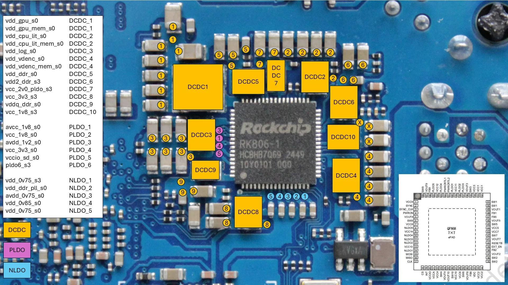
The voltage regulators are clearly structured in the device tree, and it’s relatively easy to figure out the different configuration parameters. Let’s take vdd_cpu_big0 for example:
- vin-supply = <0x87> => vcc5v0-sys provides the input voltage for this regulator
- regulator-min-microvolt = <0x86470> => the minimum voltage is 550 mV
- regulator-max-microvolt = <0x100590> => the maximum voltage is 1050 mV
- phandle = <0x18> => this is the phandle of the regulator, which we find is linked to nodes cpu@400 and cpu@500
Unlocking the Operating Voltage Range
Increasing the operating voltage is, again, not that complicated, but I’ll walk you through the process so you can understand how we get there.
For this strategy, we focus on the voltage rails that power IP blocks with PVTPLL clocking. That includes:
- vdd_cpu_big0: A76 Cluster0 and NPU
- vdd_cpu_big1: A76 Cluster1
- vdd_cpu_lit: A55 Cluster and DSU
- vdd_gpu: GPU
From the RK806 and RK860 datasheets, we find the following specifications.
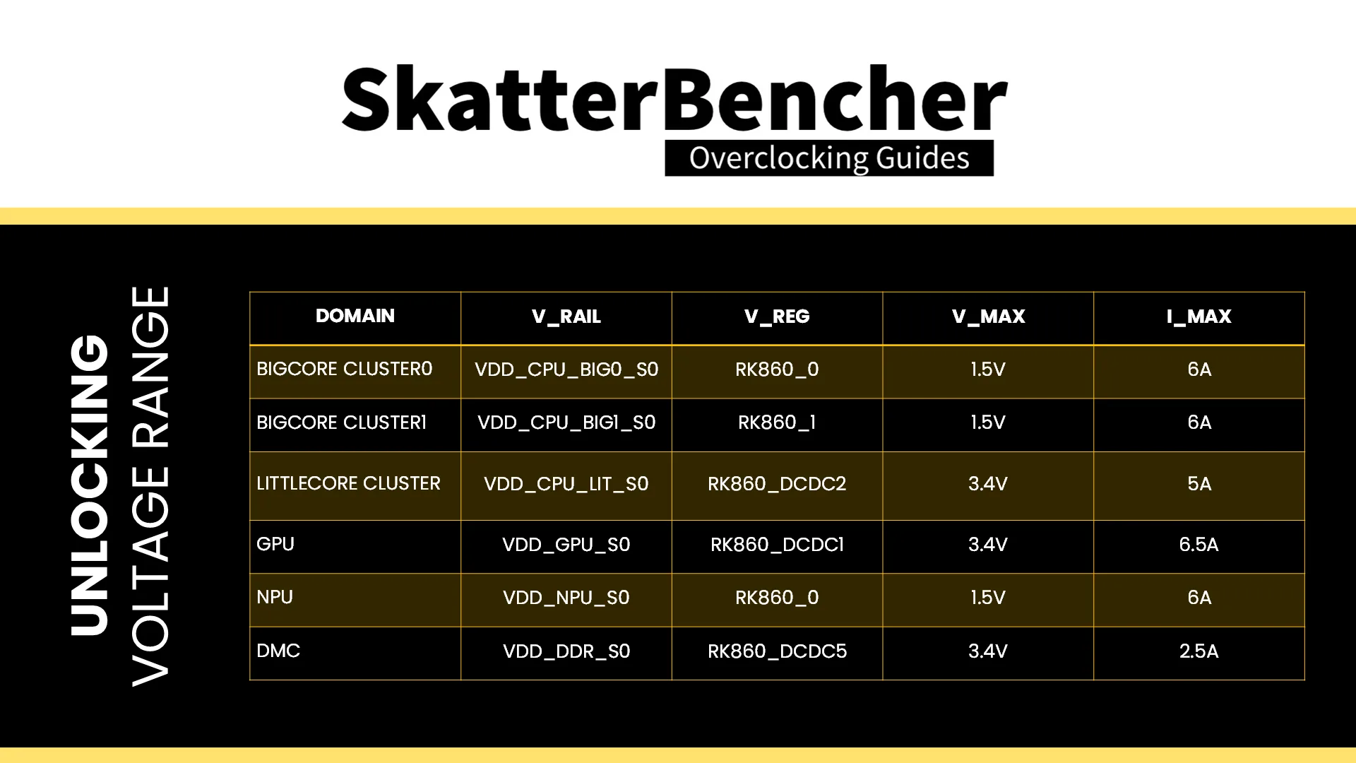
Based on this, I decided to set the regulator-max-microvolt for every rail to 1.5V.
Then, to make sure we can use the additional voltage headroom, we must also update the OPP tables. Here, I configure the CPU Clusters and GPU to allow up to 1.5V. We can do that by changing the third and sixth value for each opp-microvolt to 1.5V.
To make my life a bit easier, I created a new “unlocked” device tree based on our modified DTB from OC Strategy #2 with the following modifications:
For cluster0-opp-table entry:
- Remove all opp-j-m entries
- Remove all opp-microvolt-Lx entries
- Set all opp-supported-hw to <0xff 0xfff>
- Set all opp-microvolt entries to 1.5V (0x16e360) maximum voltage
For cluster1-opp-table and cluster2-opp-table:
- Remove all opp-j-m entries
- Remove all opp-microvolt-Lx entries
- Set all opp-supported-hw to <0xff 0xfff>
- Set all opp-microvolt entries to 1.5V (0x16e360) maximum voltage
For gpu-opp-table:
- Remove all opp-j-m entries
- Remove all opp-microvolt-Lx entries
- Set all opp-supported-hw to <0xff 0xfff>
- Set all opp-microvolt entries to 1.5V (0x16e360) maximum voltage
For rk8602@42 and rk8602@43:
- Set regulator-max-microvolt to 1.5V (0x16e360)
For DCDC_REG1, DCDC_REG2, and DCDC_REG5
- Set regulator-max-microvolt to 1.5V (0x16e360)
Similarly, you can also clean up the DMC OPP table if you wish.
Increasing the Operating Voltage
The next step is to start trying higher voltages. For this, we can use a simple device tree overlay. I decided to create one overlay for the CPU cores and one for the GPU, so I can enable them separately.
CPU PVTPLL OV Device Tree Overlay
This is my template for the CPU core PVTPLL overvolting device tree overlay.
/dts-v1/;
/plugin/;

/ {
    fragment@0 {
        target = <&cluster0_opp_table>; // Little Cores 0-4
        __overlay__ {
            opp-1800000000 {
                opp-microvolt = <1250000 1250000 1500000 1250000 1250000 1500000>;
            };
        };
    };

    fragment@1 {
        target = <&cluster1_opp_table>; // Big Cores 0-1
        __overlay__ {
            opp-2400000000 {
                opp-microvolt = <1300000 1300000 2000000 1300000 1300000 2000000>;
            };
        };
    };

    fragment@2 {
        target = <&cluster2_opp_table>; // Big Cores 2-3
        __overlay__ {
            opp-2400000000 {
                opp-microvolt = <1300000 1300000 2000000 1300000 1300000 2000000>;
            };
        };
    };
};
GPU PVTPLL OV Device Tree Overlay
This is a template for the GPU PVTPLL overvolting device tree overlay.
/dts-v1/;
/plugin/;

/ {
    fragment@0 {
        target = <&gpu_opp_table>;
        __overlay__ {
            opp-1000000000 {
                opp-microvolt = <1100000 1100000 1500000 1100000 1100000 1500000>;
            };
        };
    };
};
Before we start experimenting, make sure to move the unlocked dtb and overclock dtbos to the appropriate folders:
- sudo cp rk3588-orangepi-5-max_unlock.dtb /boot/dtb/rockchip
- sudo cp rk3588_cpu_oc_1000_1100_1100.dtbo /boot/overlay-user
- sudo cp rk3588_gpu_oc_1200.dtbo /boot/overlay-user
And add the appropriate lines to our orangepiEnv.txt configuration file.
- fdtfile=/rockchip/rk3588-orangepi-5-max_unlock.dtb
- user_overlays=rk3588_cpu_oc_1000_1100_1100 rk3588_gpu_oc_1200
Then lastly, after a system reboot, make sure to verify that the increased voltages are actually applied using the telemetry tool.
Testing PVTPLL Overvoltage
To keep the testing simple, I created multiple device tree overlays for various CPU and GPU overclocking configuration.
For the CPU cores, I found the limiting benchmark to be Jeff Geerling’s High Performance Linpack Benchmark. With the Raspberry Pi 5 official USB Type-C power supply, the Orange Pi 5 Max would shut down at around 33W from the wall socket. With the Kenengjia USB Type-C power brick, I see up to almost 40W power draw. That’s with 1.3V for the A76 cores, 1.25V for the A55 cores, and an operating temperature of about 70 degrees Celsius.
For the GPU, unfortunately, I didn’t find a more stressful working test than GLMark2-ES2. I could increase the GPU voltage to 1.10V.
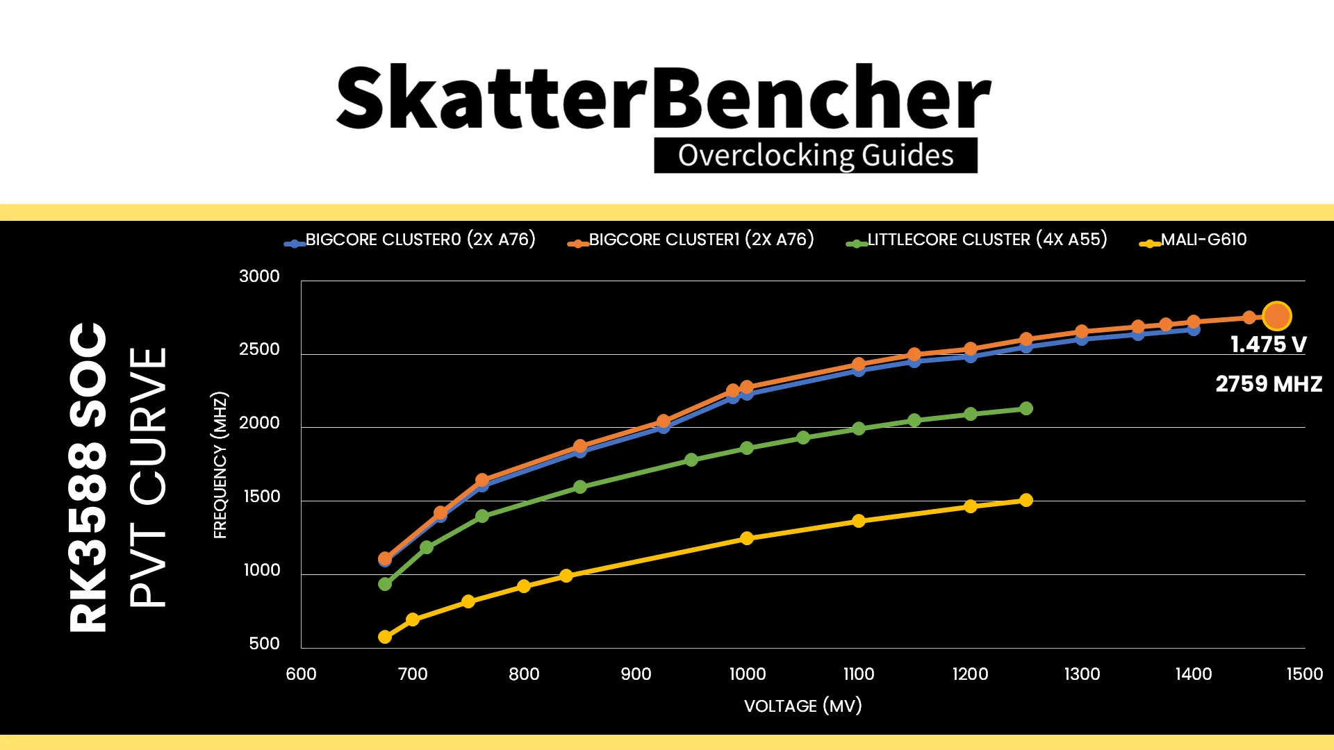
I did spend a little more time trying out higher voltages to map out the V/F curves.
- A76 Cluster0 gets to 2669 MHz at 1.400V
- A76 Cluster1 gets to 2759 MHz at 1.475V
- A55 Cluster gets to 2123 MHz at 1.25V
- Mali-G610 gets to 1507 MHz at 1.25V


Benchmark Results
We rerun the benchmarks and check the performance increase compared to the default operation.
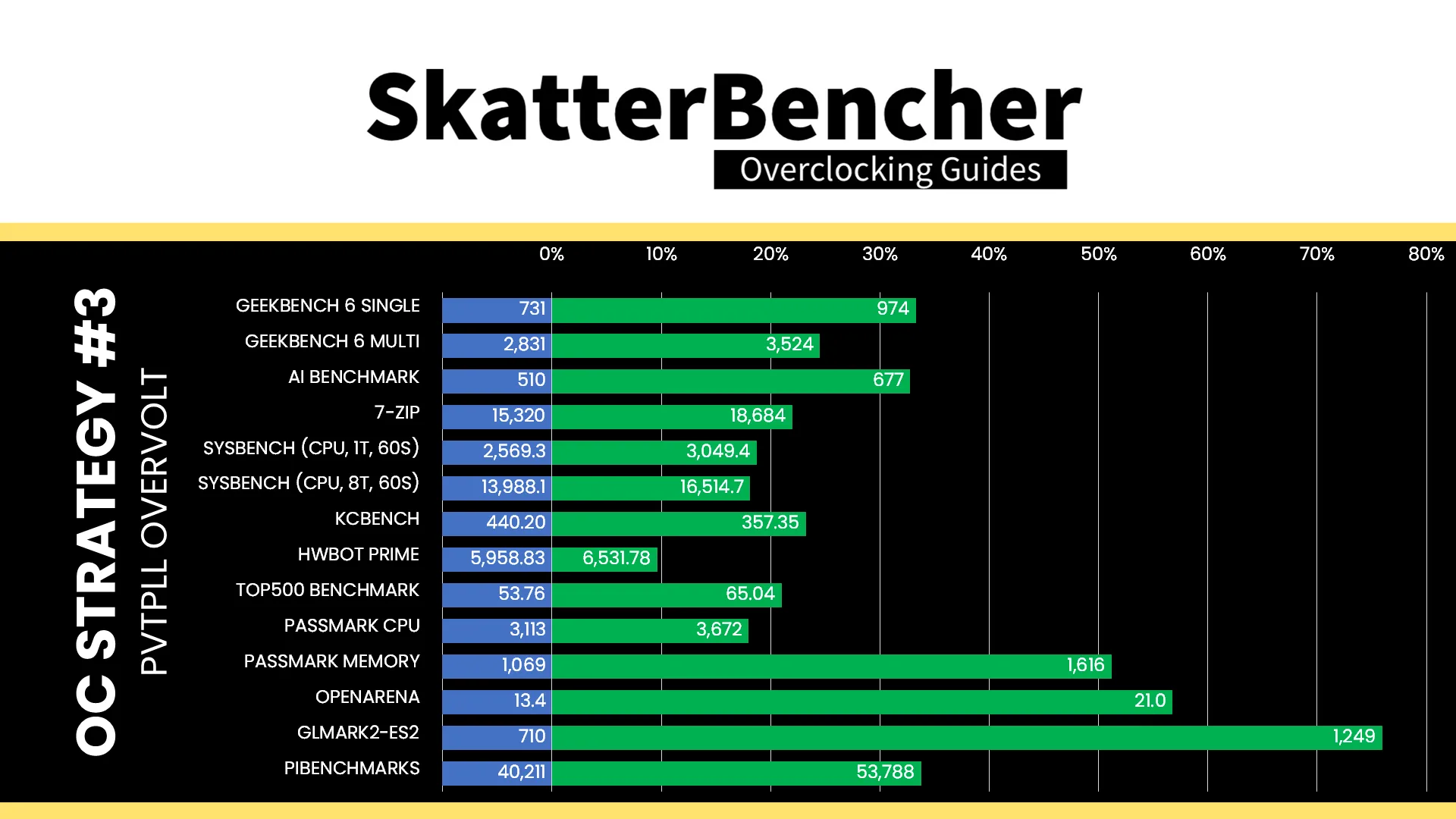
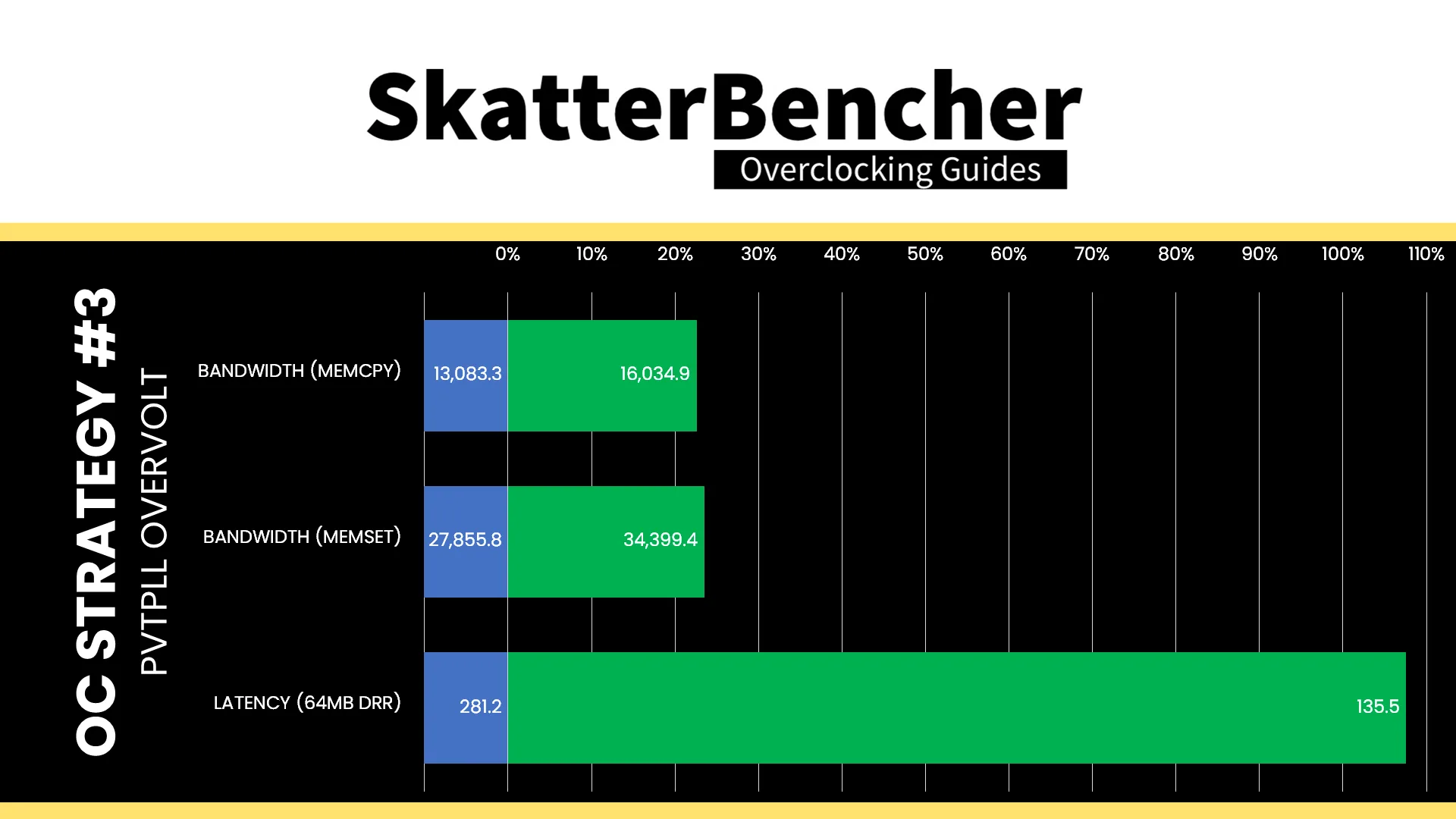
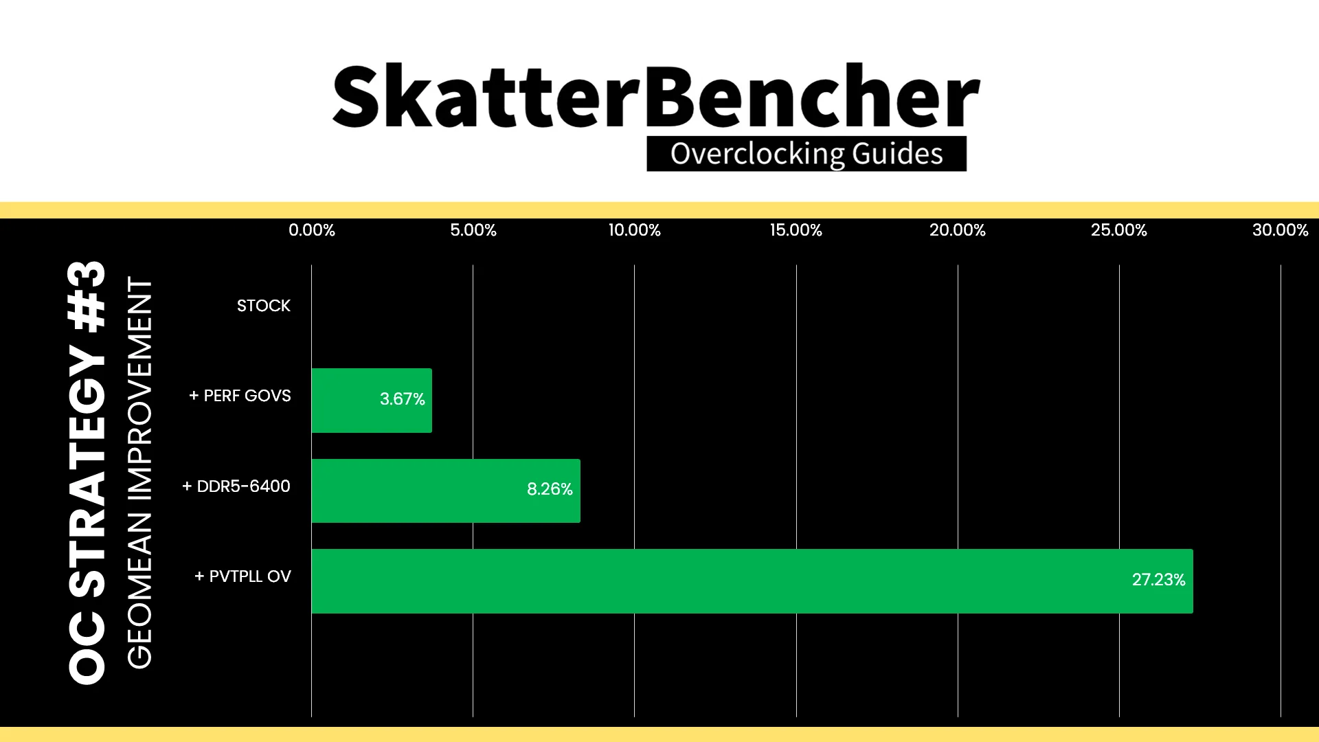
Obviously, increasing the CPU core, DSU, and GPU operating frequency has a direct impact on the benchmark performance, and we see improvements across the board. The Geomean performance improvement over stock is now +27.23%, and we get a maximum benchmark performance improvement of +75.92% in GLMark2-ES2.
When running the S-TUI Stability Test, the average A55 Cluster clock is 2099 MHz with 1.25 volts, the average A76 Cluster0 clock is 2556 MHz with 1.300 volts, and the average A76 Cluster1 clock is 2601 MHz with 1.300 volts. The average SoC temperature is 52.0 degrees Celsius. The approximate wall power consumption is 21 watts.

OC Strategy #4: Manual Overclock
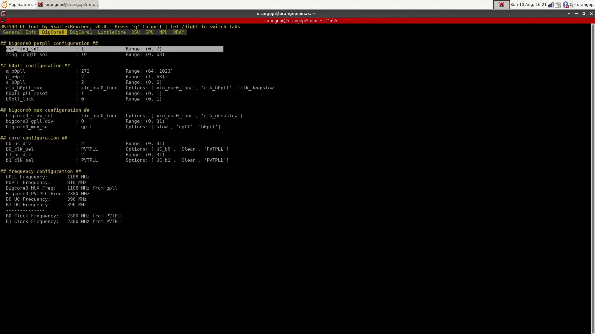
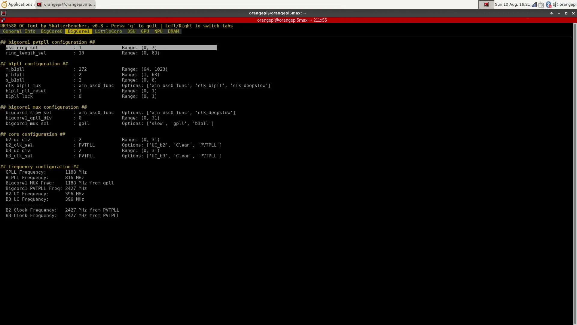
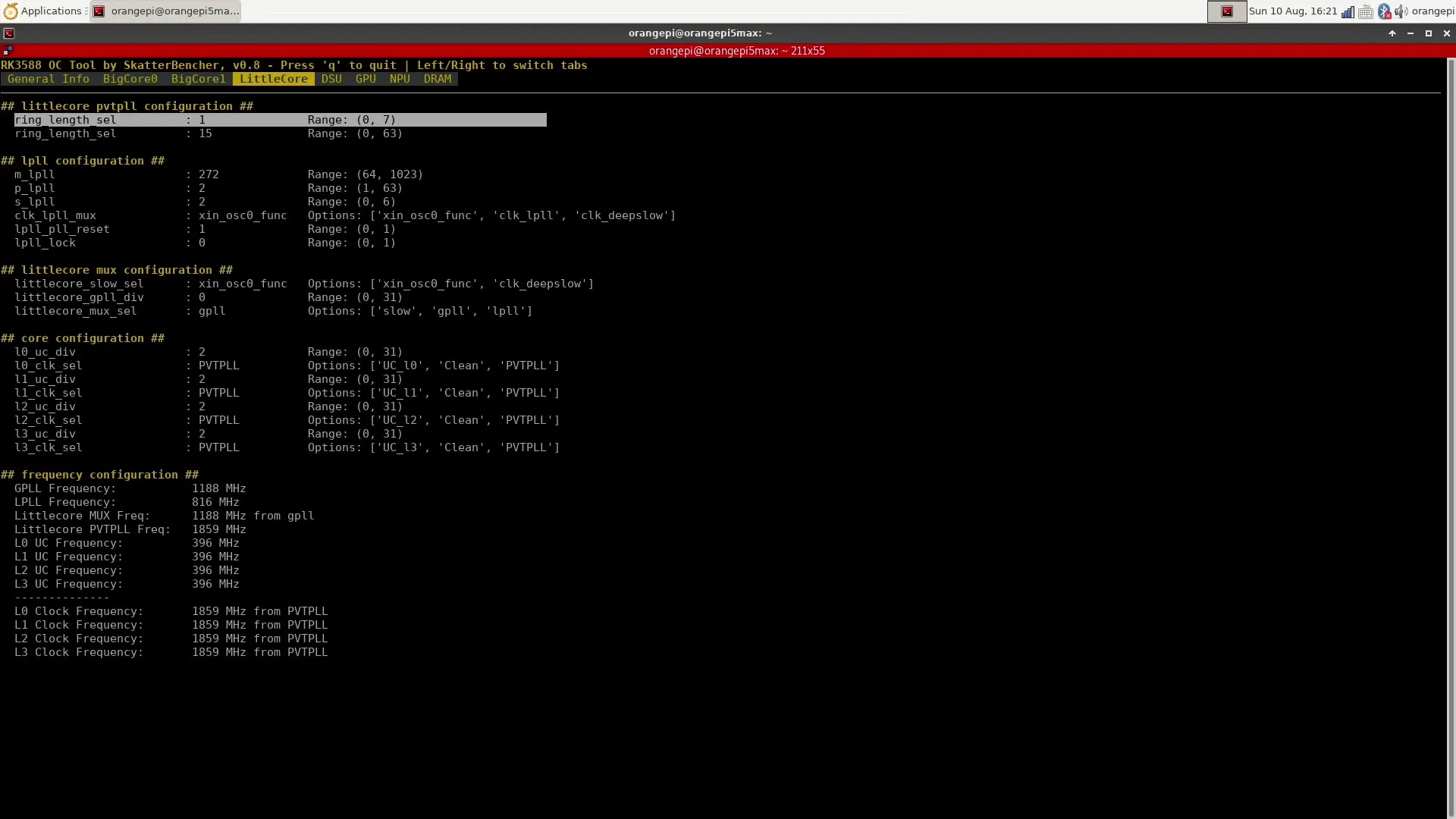
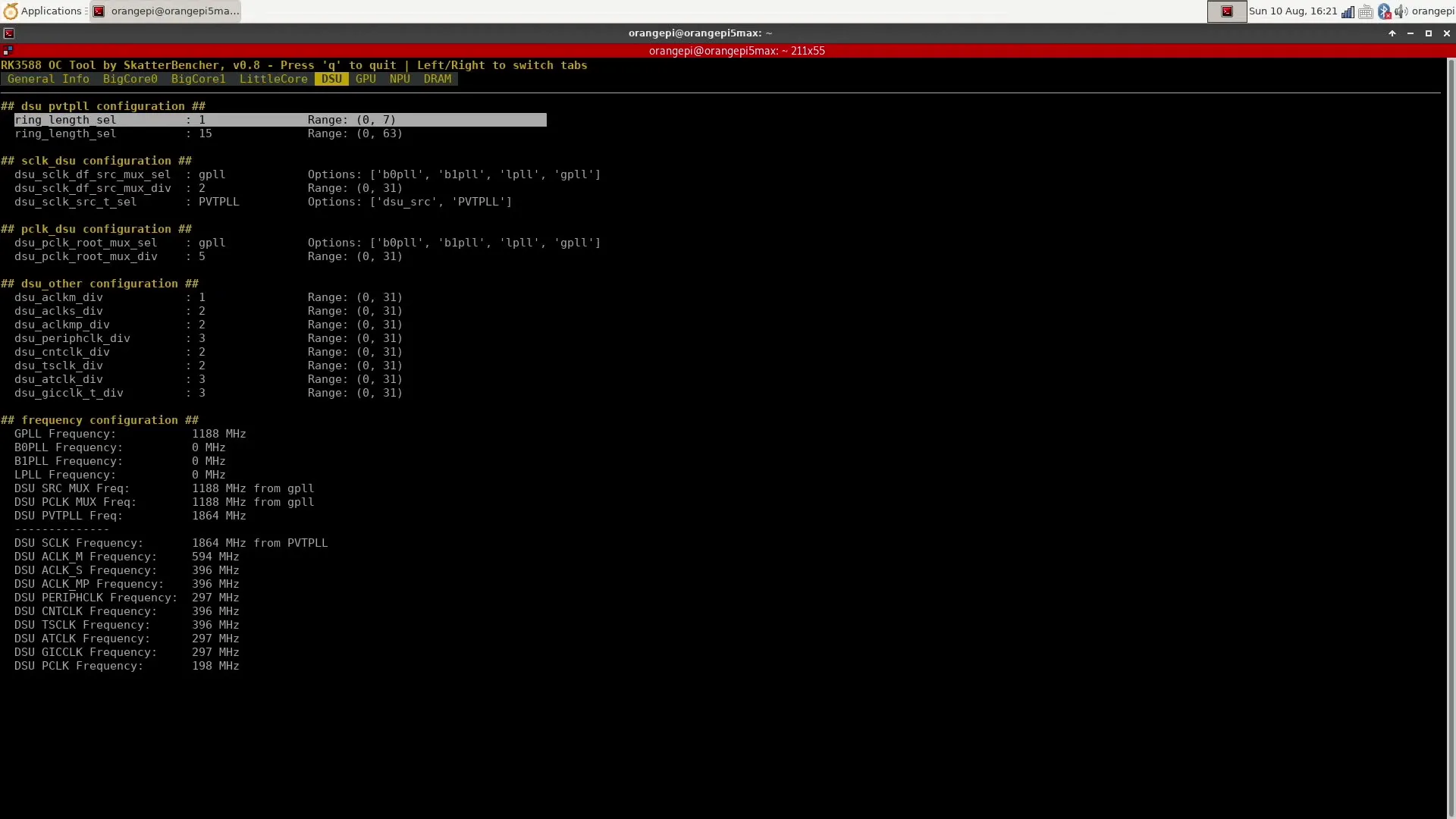
In the final overclocking strategy, we attempt to override the PVTPLL target frequencies and go for a manual overclock. For this purpose, I decided to build my own overclocking tool.
RK3588 Clocking Topology
The Rockchip RK3588 SoC uses a 24 MHz crystal oscillator as a source for the clock tree. This is the source for the 18 PLLs used by the SoC to clock the various IP blocks. The PLLs include several general PLLs used across the SoC and specific PLLs for specific IP blocks.
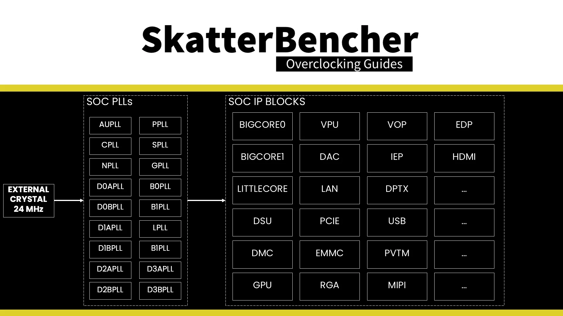
Each IP block typically has a number of clock sources to choose from.
For example, A76 core0 can be clocked by the bigcore0 shared PVTPLL or clocked separately using the b0pll and the core-specific UC divider. Similarly, the GPU can be clocked using the GPU-specific PVTPLL or derived from any of five general PLLs adjusted with a GPU-specific divider.
The clock tree can be configured at runtime by writing directly to the SoC’s CRU and GRF registers.
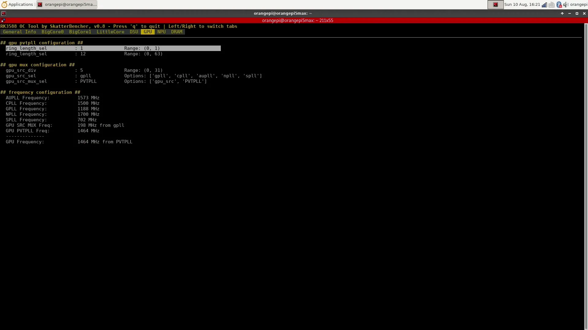
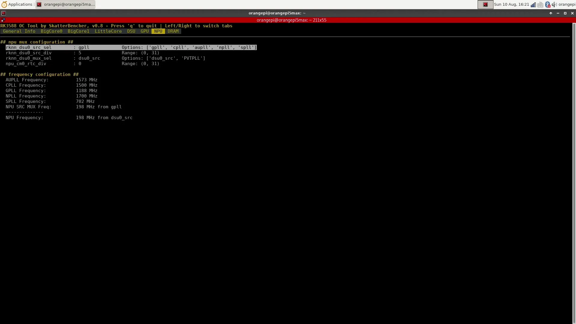
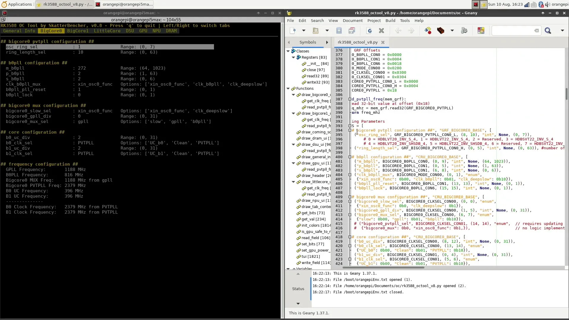
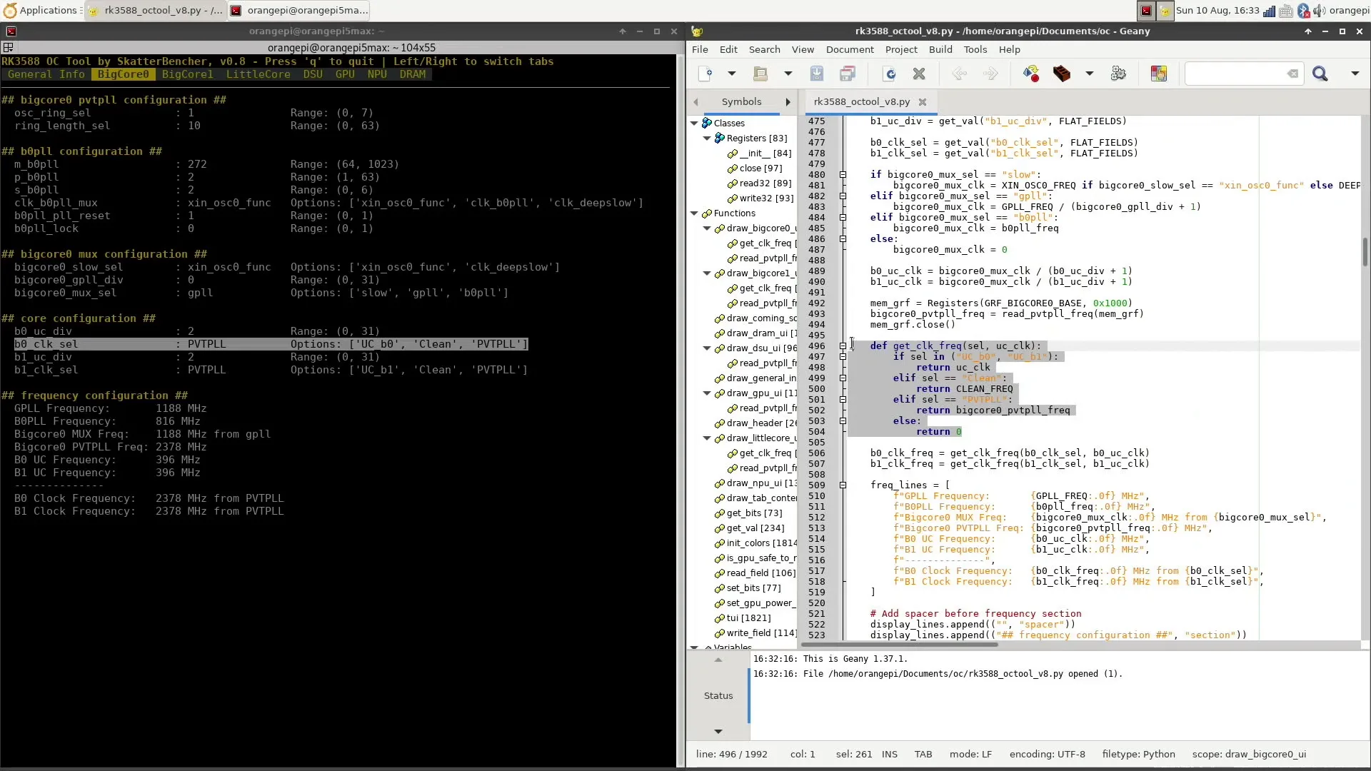
RK3588 Clock Config Tool
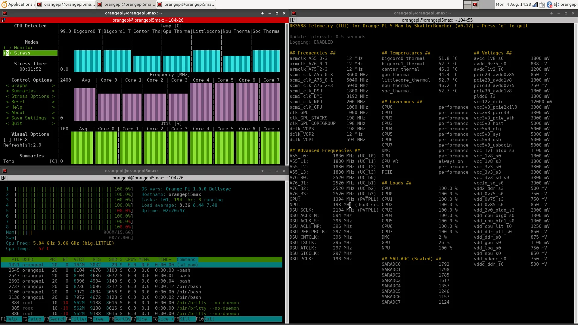
I developed a tool that can configure many parameters related to the clocking of the RK3588, including the CPU cores, DSU, GPU, and NPU. It has options for both the PVTPLL as well as non-PVTPLL clocking methods, which I’ll cover in just a bit. Again, I’ll share the code on my GitHub so you can try it out as well.
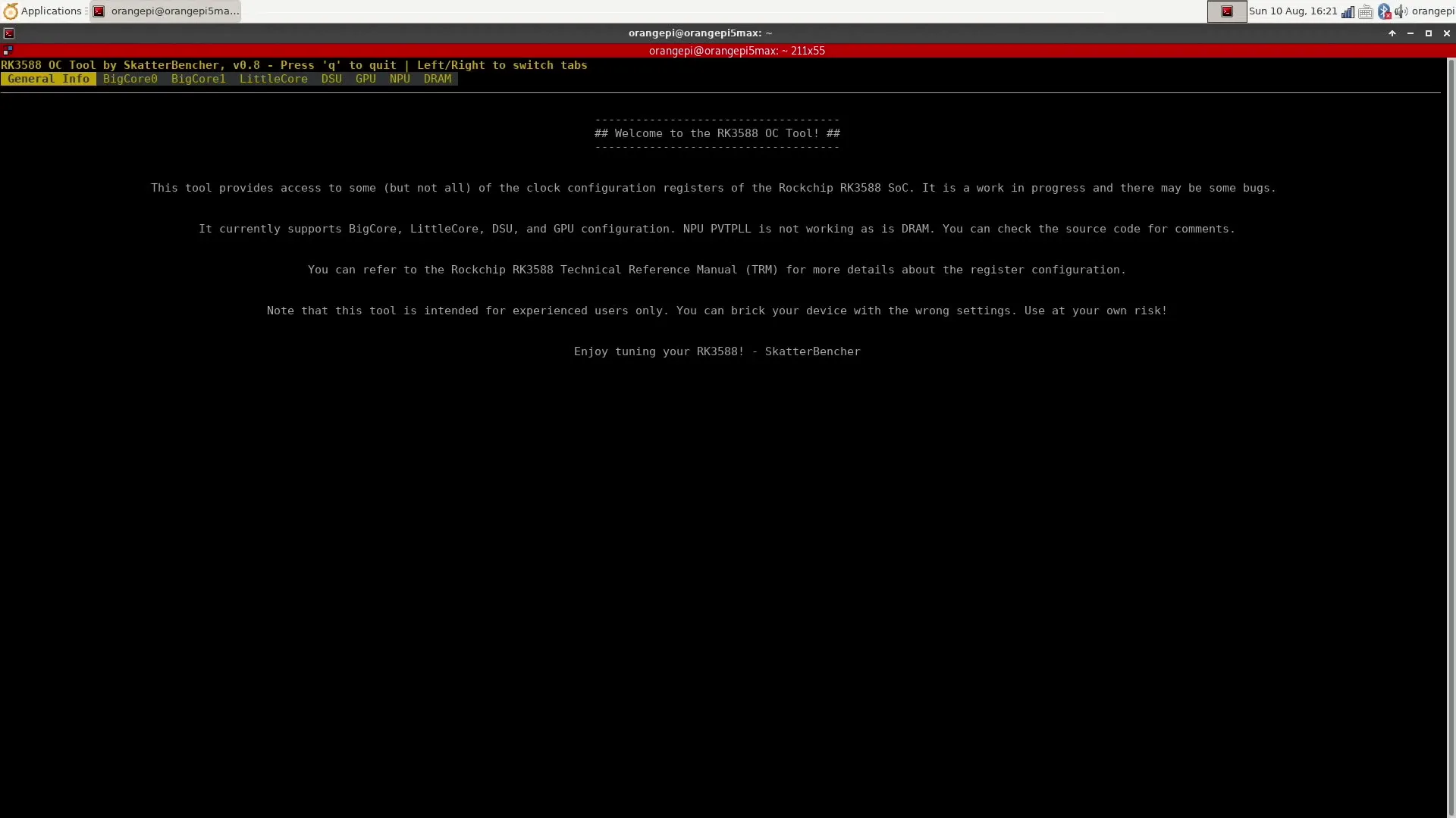
Please be aware that this is very much an advanced tool and could potentially harm your device since values are immediately applied upon pressing ‘enter’. Also, there might be some bugs here and there, and there are still parts of the tool that are work-in-progress. So, use the tool at your own risk.
Generally speaking, there are two methods to overclock the IP domains with PVTPLL support: you can tune the PVTPLL, or you can use a different PLL.
RK3588 PVTPLL Tuning
We already figured out that we can increase the performance of the PVTPLL domains by overvolting, as the adaptive clocking technology increases the operating frequency accordingly. Unfortunately, there are not a lot of knobs available to finetune the PVTPLL frequency like the “Curve Optimizer” we have for AMD’s Precision Boost technology.
As far as I can see, there are two options for tuning the PVTPLL:
- We can change the oscillator type, and
- We can adjust the oscillator ring length.
The oscillator type lets us swap different oscillators to generate the frequency. For example, for the CPU cores, we can pick between six types of oscillators:
- 0 = HDBLVT20_INV_S_4
- 1 = HDBLVT22_INV_S_4,
- 2 = Reserved,
- 3 = HDBSVT22_INV_S_4
- 4 = HDBLVT20_INV_SHSDB_4,
- 5 = HDBLVT22_INV_SHSDB_4,
- 6 = Reserved, and
- 7 = HDBSVT22_INV_SHSDB_4
I don’t quite know how to decode these oscillator types, unfortunately.
The oscillator ring length determines the number of stages in the oscillator ring. The more stages, the longer the signal delay, and so the lower the operating frequency. Both parameters work in tandem as they affect the signal delay through the oscillator circuit and, ultimately, the clock frequency.
Let’s take BigCore1 as an example.
At 1.0V, the operating frequency ranges between 2072 and 2330 MHz depending on the oscillator type. Then, with the default oscillator type (HDBLVT22_INV_S_4), the frequency ranges between 735 MHz with a ring length of 63 and 2272 with a ring length of 10.
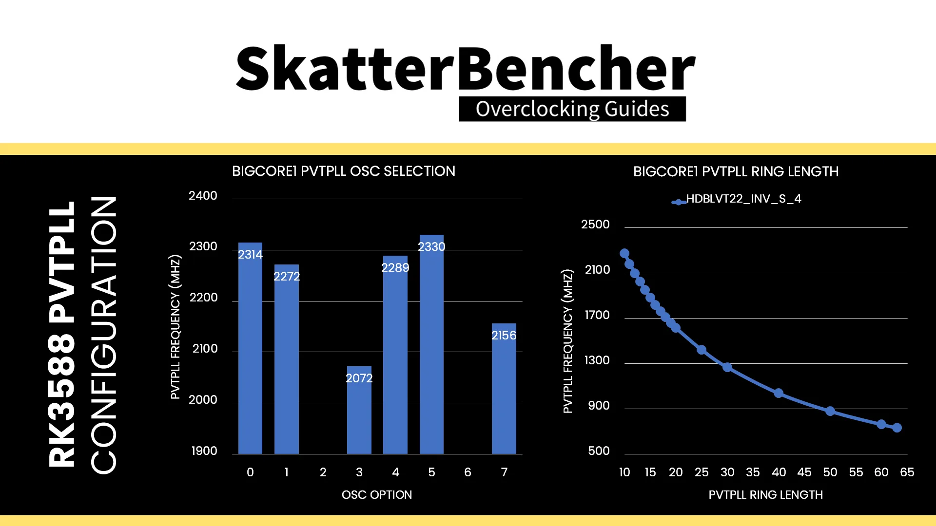
All CPU cores and the DSU have the same 6 available PVTPLL types, whereas the GPU and NPU only have two. For the GPU, here’s the operating frequency at 1.1V with each type of oscillator. The maximum frequency is slightly over 1.4 GHz.
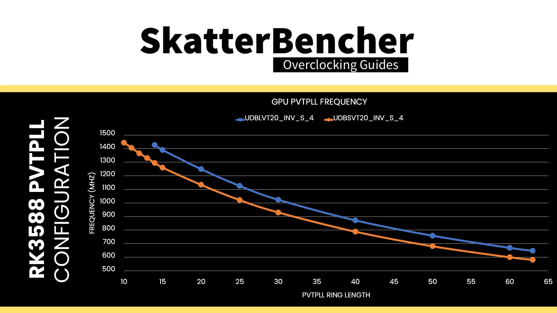
Unfortunately, I couldn’t quite get much extra frequency from PVTPLL tuning. Changing to different oscillator types wasn’t stable, and only for the GPU, I was able to reduce the ring length by 1 step. That gave us an extra 40 MHz, bumping up the clock from 1365 MHz to 1405 MHz.

RK3588 Non-PVTPLL Tuning
As I outlined in the RK3588 clocking topology section, for each of the PVTPLL domains, there’s also an alternative, more classical approach to clock configuration derived from a crystal reference clock. You can find the various tunable parameters in my clocking tool as well.
Let’s take two examples: BigCore0 and the GPU.
RK3588 BigCore0 Clocking Example
The BigCore0 operating frequency is decided by a multiplexer (or “Mux”) selecting between three clocking options: UC, Clean, and PVTPLL. I don’t know what UC stands for – maybe Universal or User Clock – but that’s the clock we pick when manually controlling the output frequency.
The UC clock itself is a function of the selection of one of the three available clock sources (“slow”, “gpll”, and “b0pll”), then divided by a core-specific UC divider.
Slow, in this case, means derived from the 24 MHz crystal and is used for idle or sleep states.
GPLL stands for General PLL, and is a clock source that’s widely used across the many RK3588 SoC IP blocks. It’s defined as running at 1188 MHz and is derived from the 24 MHz crystal oscillator. Technically, we could adjust the GPLL frequency to run at a different frequency. But that would affect a lot of parts of the SoC, so it’s not recommended.
B0PLL is a reference clock specifically used for the BigCore0 cluster and the preferred source for our manual overclocking attempts. It is also derived from the 24 MHz crystal and uses one multiplier “m” with two dividers “p” and “s” to generate the final B0PLL frequency.
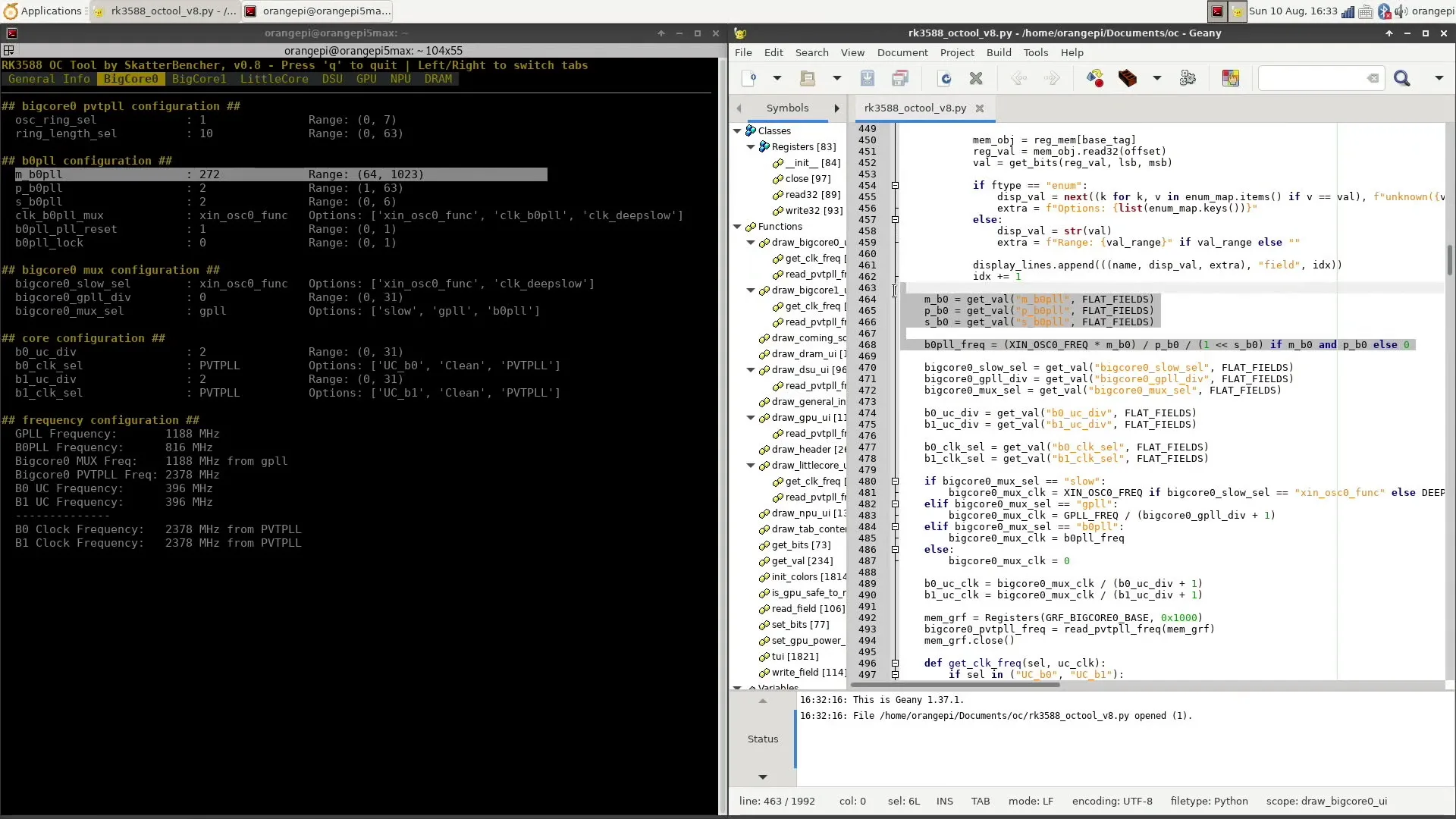
For example, if m = 400, p = 2, and s = 1, then the calculation is as follows: [(24 MHz x 400) / (2 x (1+1))] = 2400 MHz. The ultimate BigCore0 core frequency is then 2400 MHz B0PLL divided by the core-specific UC divider. For example, if the divider is 2, then the core frequency is 2400 MHz / 2 = 1200 MHz.
The clock tree for BigCore1 and LittleCore clusters is very similar, with the exception that the reference clock includes B1PLL and LPLL, respectively. All three reference clocks are also available to the DSU SCLK and PCLK, in addition to the GPLL.
RK35888 Mali-G610 Clocking Example
The GPU clocking is a bit simpler as it lacks a user-configurable reference clock. Instead, the GPU clock can be derived from several general clock sources available in the RK3588 SoC, including: AUPLL, CPLL, GPLL, NPLL, and SPLL.
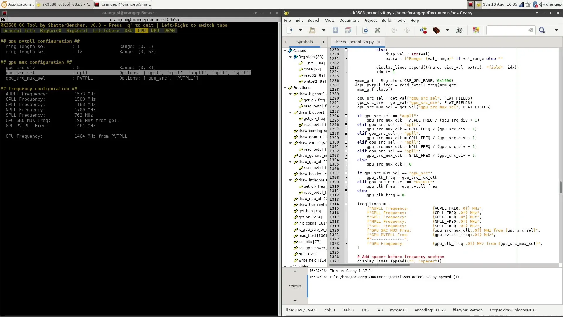
As I mentioned, each of these reference clocks could technically also be adjusted, but it could affect various other IP blocks in the SoC. After selecting one of the available reference clocks, the frequency gets divided by a GPU-specific divider before yielding the ultimate operating frequency.
Manual Fine-Tuning
As I already mentioned, for the GPU, I was able to squeeze a little higher frequency using the PVTPLL tuning approach. However, for the other domains, there was no headroom.
So, I tried to apply a manual “UC” overclock for the A55 and A76 cores with the same 1.25V and 1.30V from the previous OC strategy. I hoped that the PVTPLL technology would be conservative and, thus, there would be some overclocking headroom. Unfortunately, it seems that the PVTPLL is pretty good at extracting the highest possible frequency because I couldn’t match the operating frequency for any of the cores.
In fact, the A55 cores could only clock up to 1830 MHz, which is 150 MHz less than what PVTPLL gave at 1.25V. The A76 cores could clock up to 2520 MHz, which is 40 MHz higher than PVTPLL for the BigCore0 cluster and 80 MHz lower for the BigCore1 cluster.
Now, bear in mind that the PVTPLL is an adaptive clocking technology, meaning the frequency will adapt to the workload intensity. If we run Jeff Geerling’s High Performance Linpack workload with the PVTPLL configuration from OC Strategy #3, we find that the A76 Cluster0 frequency drops all the way to 2518 MHz, and the A76 Cluster1 frequency drops to 2561 MHz.
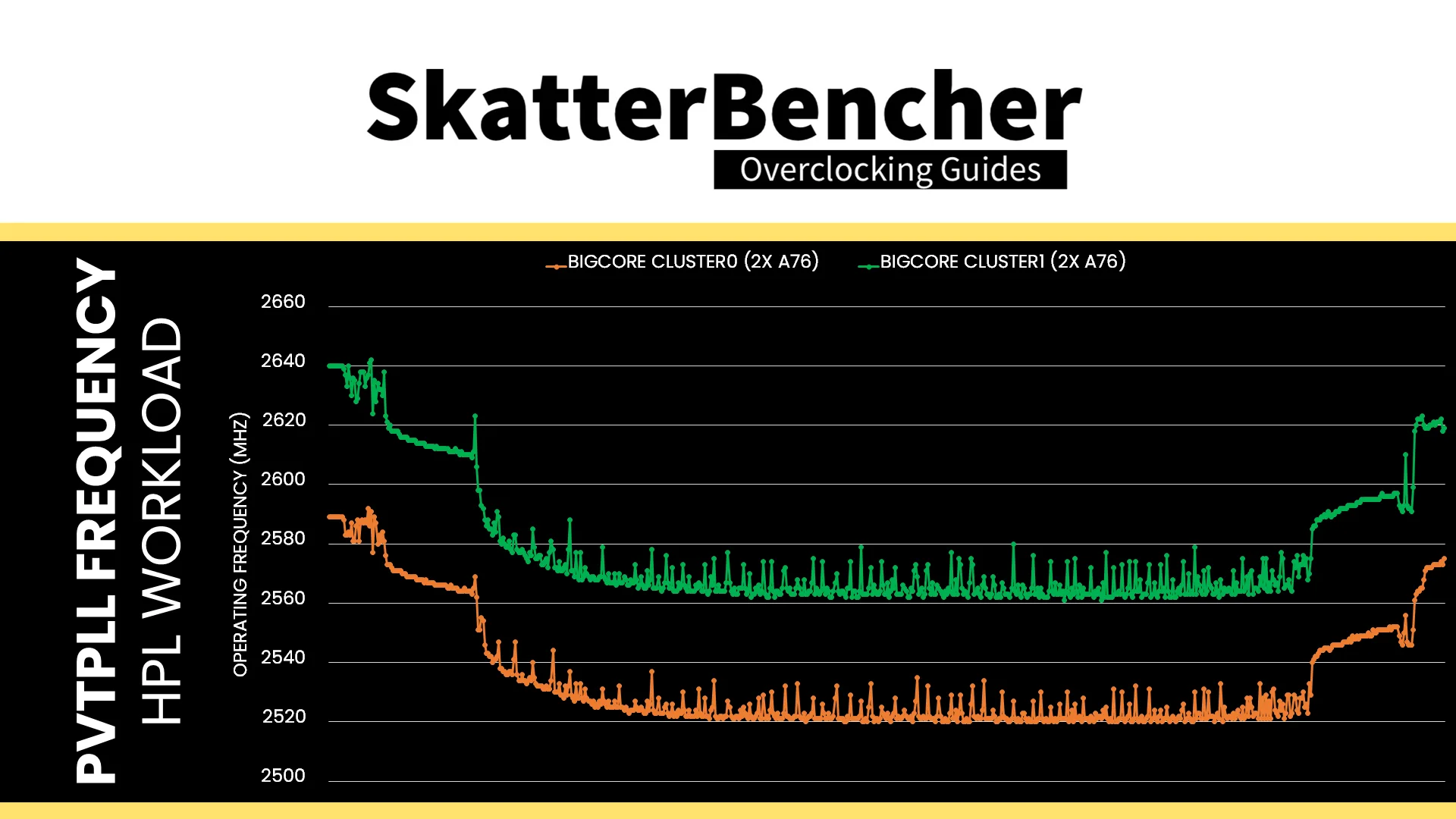
That makes our manual overclocking results seem a lot more reasonable.
OC Settings & Benchmark Results
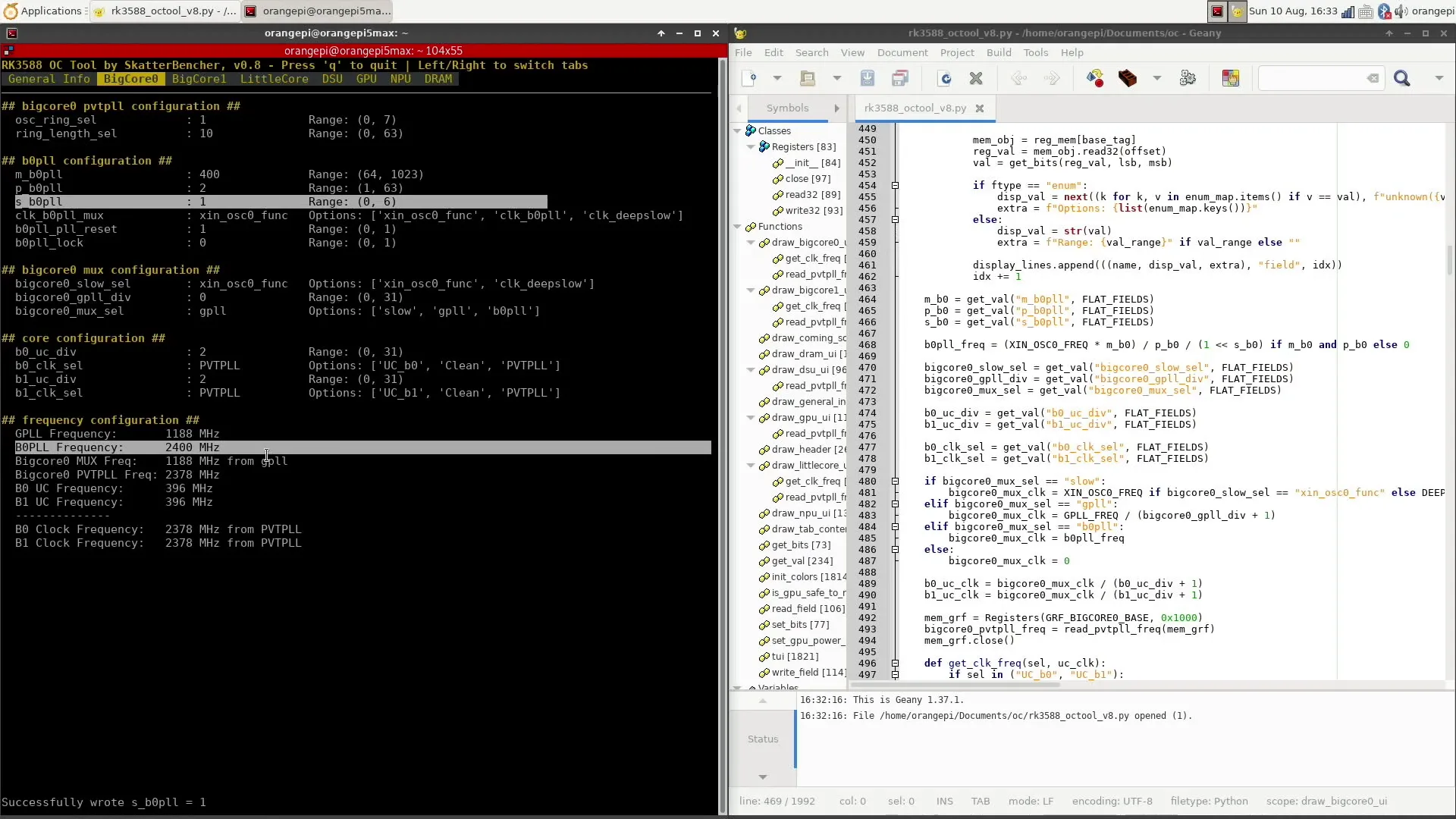
Upon opening the RK3588 OC Tool
- Go to the BigCore0 tab
- Set m_b0pll to 420
- Set p_b0pll to 2
- Set s_b0pll to 0
- Set b0pll_pll_reset to 0
- Set bigcore0_mux_sel to b0pll
- Set b0 and b1_uc_div to 1
- Set b0_clk_sel to UC_b0
- Set b1_clk_sel to UC_b1
- Switch to the BigCore1 tab
- Set m_b1pll to 420
- Set p_b1pll to 2
- Set s_b1pll to 0
- Set b1pll_pll_reset to 0
- Set bigcore1_mux_sel to b1pll
- Set b2 and b3_uc_div to 1
- Set b2_clk_sel to UC_b2
- Set b2_clk_sel to UC_b3
- Switch to the LittleCore tab
- Set m_lpll to 305
- Set p_lpll to 2
- Set s_lpll to 0
- Set lpll_pll_reset to 0
- Set litlecore_mux_sel to lpll
- Set l0 to l3_uc_div to 1
- Set l0_clk_sel to UC_l0
- Set l1_clk_sel to UC_l1
- Set l2_clk_sel to UC_l2
- Set l3_clk_sel to UC_l3
- Switch to the DSU tab
- Keep dsu_sclk_src_sel to PVTPLL
- Switch to the GPU tab
- Set ring_length_sel to 11
- Keep gpu_src_mux_sel to PVTPLL
We rerun the benchmarks and check the performance increase compared to the default operation.
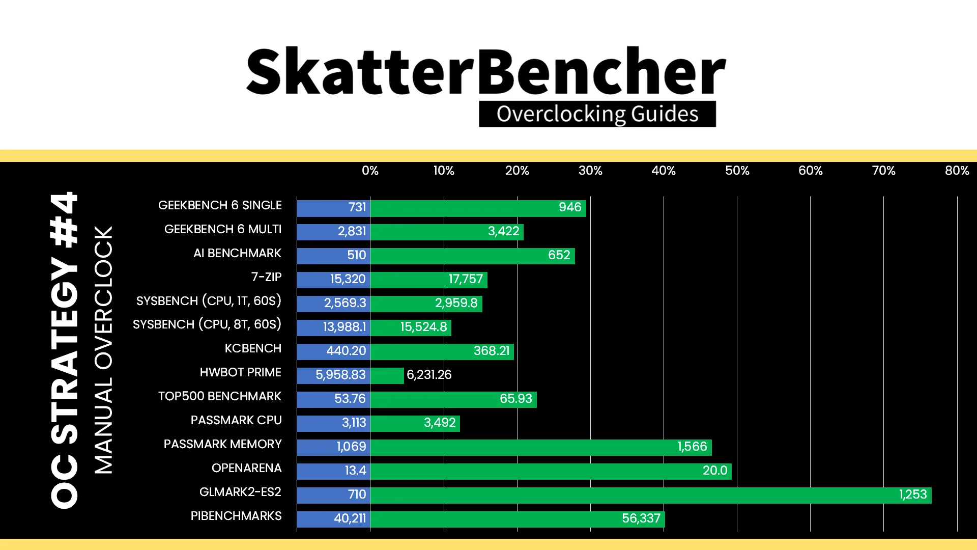
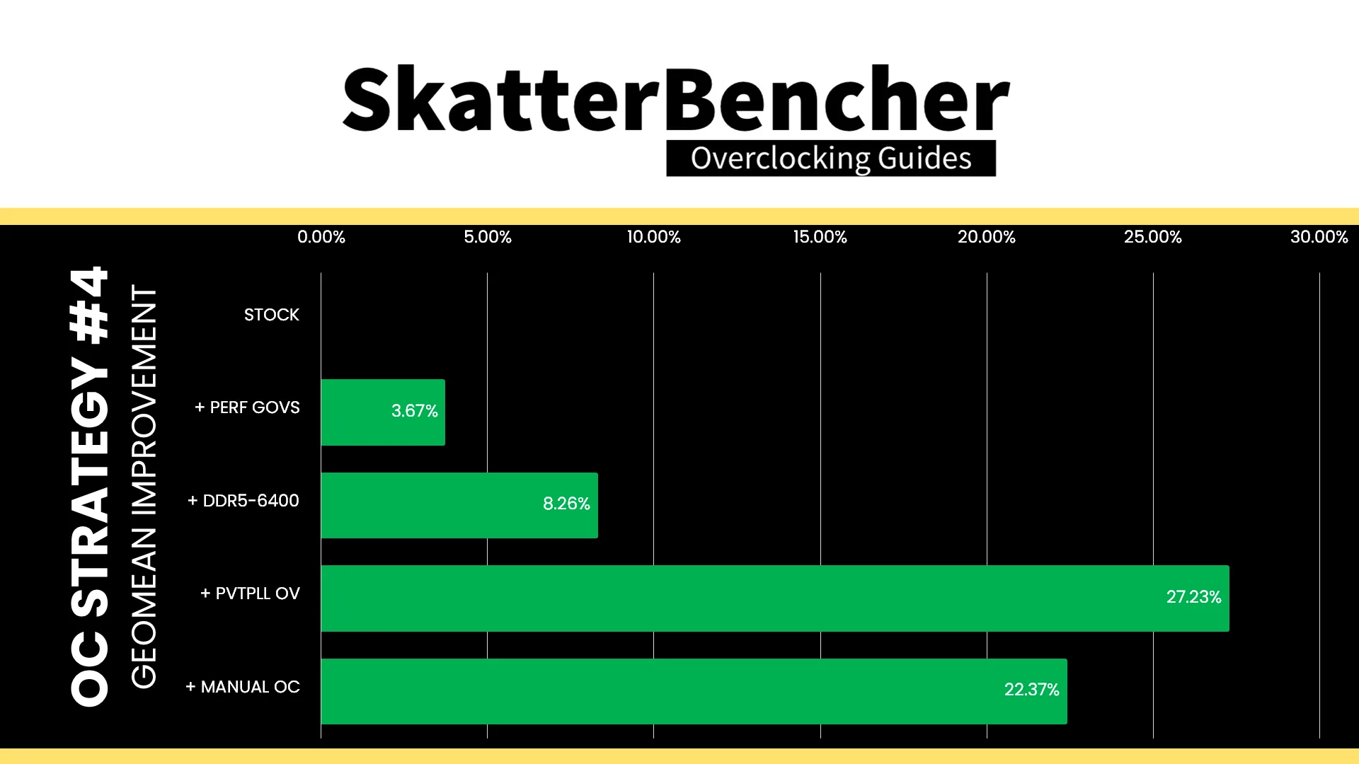
The slightly lower frequencies than our previous OC Strategy translate into slightly lower benchmark performance, though still significantly higher than stock. We still have some slight improvement in the HPL Benchmark and GLMark2-ES2. The Geomean performance improvement over stock is +22.37%, and we get a maximum benchmark performance improvement of +76.48% in GLMark2-ES2.
When running the S-TUI Stability Test, the average A55 Cluster clock is 1830 MHz with 1.25 volts, the average A76 Cluster0 and Cluster1 clock is 2520 MHz with 1.300 volts. The average SoC temperature is 52.7 degrees Celsius. The approximate wall power consumption is 21 watts.
Orange Pi 5 Max: Conclusion
Alright, let’s wrap this up.
A couple of months ago, I decided to take on the Orange Pi 5 Max as my summer project, as it would put me out of my X86 comfort zone. It’s the second single-board computer I’ve overclocked on this channel, following the Raspberry Pi 5 from last year.
I learned a lot from this project: I made my own telemetry and clocking tools (with the help of AI), learned about modifying device trees, and got to play with a totally new adaptive clocking technology called PVTPLL. Overall, I thoroughly enjoyed this project and feel it was a valuable learning exercise.
Of course, there are still a lot of things to discover about this single-board computer: running the latest Linux kernel, getting full 3D graphics acceleration, using the integrated NPU, figuring out how to read the DRAM configuration, and so on. But that will be for another time, as I first want to see how the Orange Pi 5 behaves with more exotic cooling.
Anyway, that’s it for this guide.
I want to thank my Patreon supporters and YouTube members for supporting my work. If you have any questions or comments, please drop them in the comment section below.
See you next time!
markon
Hi,
I took my Rock 5B for the spin, and it look like you still left some potential in point 2 on the table – You have increased memory clock only to its rated speed.
I don’t know how lpddr5 and dmc would roll with it but I have pushed my lppdr4x to 2496Mhz from it’s “rated” 2133MHz speeds and gain some more throughput in memory benchmarks (vkpeak, clpeak, cl-mem, and I believe opencl-benchmark).
Unfortunately I cannot gain anything more without playing with voltages which I need yet to investigate (i didn’t touch dmc opp table, and It seems like DDR voltages – 1.1v and 0.6v – at first glance lacks any adjustment in dtb) next step on 2520MHz (clock increases in 24mhz steps, can be observed under I believe /sys/kernel/debug/clk/clk_summary or somewhere close) makes it unstable but probably “benchmarkable”.
jax
Great work!
Have been looking for something like this ever since I got a opi5 when they came out.
Was looking to OC/UV it w/o the over-complicated DTB hacking
A great first step in making this powerful sbc into a tuner-friendly platform like the Rpi and more!
Looking forward to updates on this
BTW, anyone played with the LPDDR4X OC freq?
2120 to 2400 OC seems stable for now
markon
I have pushed mine to 2496MHz, anything above throws errors in memtester, but I didn’t played with voltages yet (if it’s even possible)
StonedEdge
Are you using the libmali blob drivers or Mesa for these tests?
IIRC, they have different dtb entries, and control frequencies differently.
Pieter
I’m using the default blob that came with the Debian Bullseye Desktop image.
I tried changing to a different driver but was not successful probably due to lack of skill 🙂
StonedEdge
Hmm, interesting! I am using a Radxa CM5 on my system, would like to generate some form of overlay to get this to work with my RK3588s handheld. But alas, I am not too experienced when it comes to modifying this kind of low level hardware stuff 🙂 We are using the g13p0 libmali blobs.
The locations of various device trees are scattered, for example:
https://github.com/armbian/linux-rockchip/blob/rk-6.1-rkr5.1/arch/arm64/boot/dts/rockchip/rk3588-rk806-single.dtsi
https://github.com/armbian/linux-rockchip/blob/rk-6.1-rkr5.1/arch/arm64/boot/dts/rockchip/rk3588s-radxa-cm5.dtsi
https://github.com/armbian/linux-rockchip/blob/rk-6.1-rkr5.1/arch/arm64/boot/dts/rockchip/rk3588s.dtsi
Boosting the GPU at least would give me a nice performance boost in many areas for my project! Maybe I’ll figure it out soon enough… but for now I don’t want to break anything 😛
https://github.com/StonedEdge/Retro-Lite-CM5
boogie
when benchmarking gpu, the compositor limits the framerate to display framerate for too easy tests. therefore results deducted would be misleading.
i would suggest to test gpu perforamance with complete disabling the DE and run from the terminal with “glmark2-drm –off-screen”. you should also get the same/similar with “glmark2 –off-screen” since both of them will not composite anything to screen.
to even fine tune and get comparable results you might use only a heavy specific test “terrain” so that overall score will not fluctuate due to different load profiles in different tests.
ie: “glmark2 –off-screen -b terrain” or “glmark2 –off-screen -b refract” (refract test is also a heavy test.)
Joe Brampton
I am on the fence about purchasing the Max — I am staring at it in my cart every single day, teetering back and forth on it.
Graphic acceleration, and supporting 144hz output for 1440p monitor is a must!
It works for me on original Orange Pi 5, but only with very specific, ancient, legacy kernels (6.1 series)
Please let me know if you can comment sooner than later on getting graphic acceleration & high refresh rates working on a modern kernel — I’d pull the trigger right away — and need your help getting it working!
Thanks!
Pieter
Unfortunately I couldn’t get Linux mainline to work. I’m sure there’s a way but it’s not as straightforward as simply compiling the kernel.
markom
I have another board with mainline (fedora, installed as described in thread if I remember correctly “fedora on rock 5b” on radxa forum, arch Linux can also be installed following other thread from that forum, armbian images with mainline Linux are available OoB – much better option in than vendor images).
There will by more issues with overclocking, GPU clocks only in selected steps without kernel recompilation (… 850MHz, 1188MHz, 1500MHz… – mine is stable at 1188@1050mV, cannot get 1,5GHz stable).
RAM reclocking would also probably require kernel recompilation – rkddr not working, no any mentions in dtb.
And there is probably overall lack of support of PVT (didn’t have touched core clocks yet so I’m not sure if it’s for all domains or only GPU)
Steve
Just get the Orange Pi 5 Plus. All later models are very poorly supported and they won’t do anything to address it. Waste of money.