Voltage Suspension forces the CPU Core Voltage to stay within a specific range even when using a dynamic voltage like with Precision Boost Overdrive.
Voltage Suspension is a feature included in the External Digi+ Power Control menu of the BIOS. At the moment of writing, I believe it’s only available in beta BIOSes of the ASUS ROG Crosshair VIII Extreme motherboard like the 0055 I’m using for this guide. However, the feature should also make it to public BIOSes and pop up when using Vermeer CPUs.
The term suspension is akin the suspension of a car, though I prefer the more technical term V-Clamp. The purpose of V-Clamp is to force the Core Voltage to stay within a specific range even when using a dynamic voltage like with Precision Boost Overdrive.
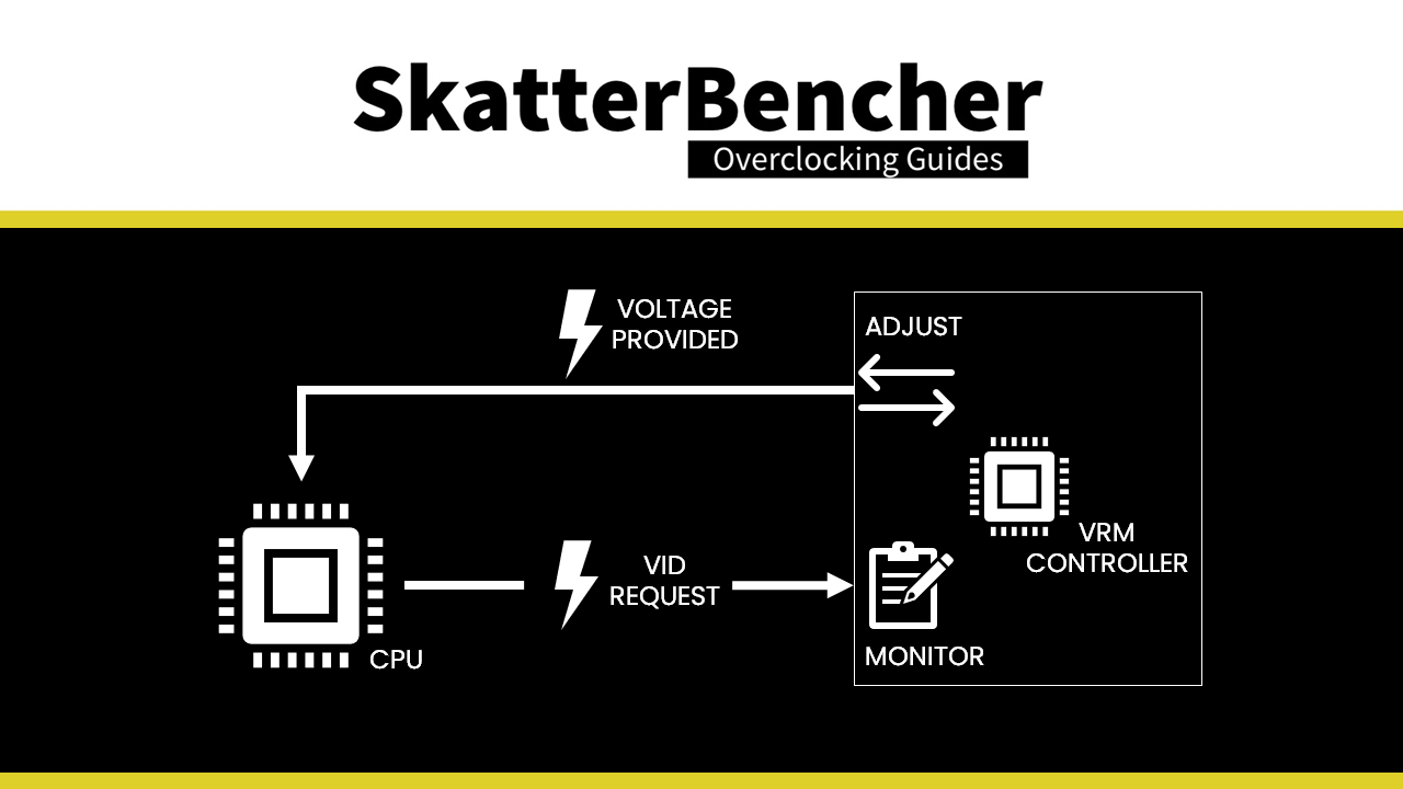
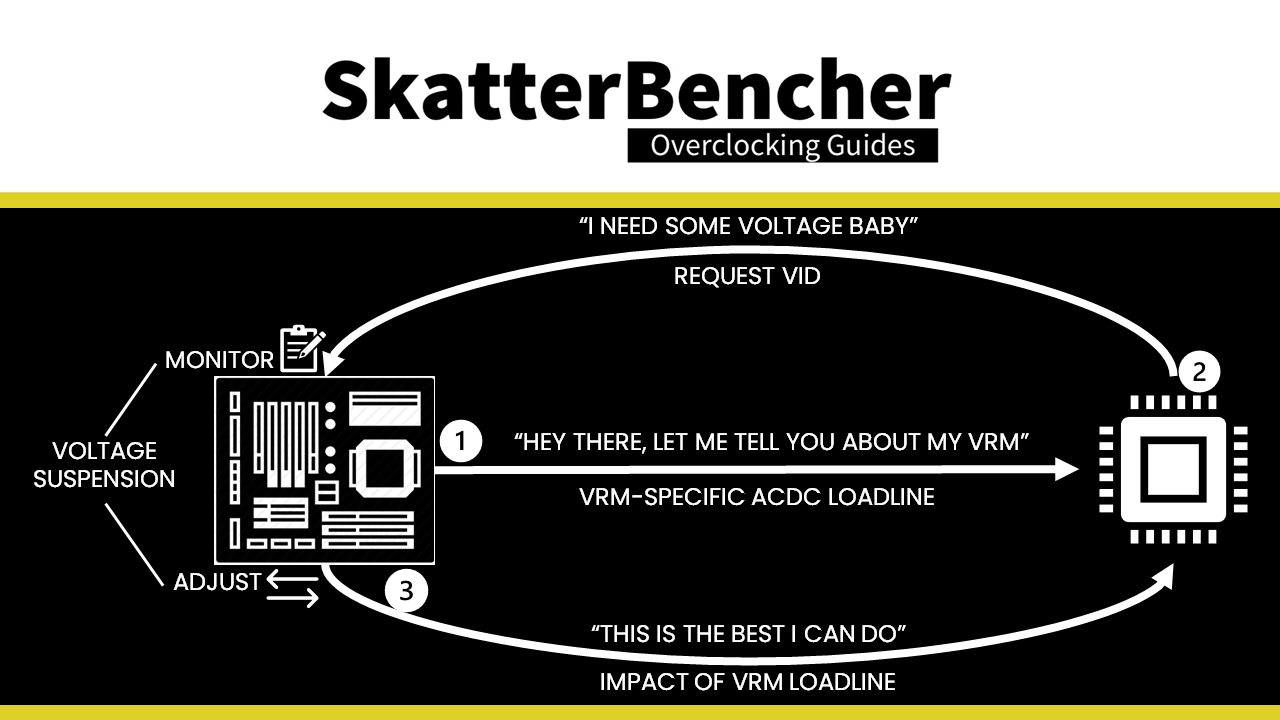
To achieve this, there’s a special hardware circuitry on the motherboard PCB. Essentially the circuitry has two main functions: one function to monitor what the CPU requests as VID (so voltage), another function to correct this request and adjust it according to our custom suspension rules.
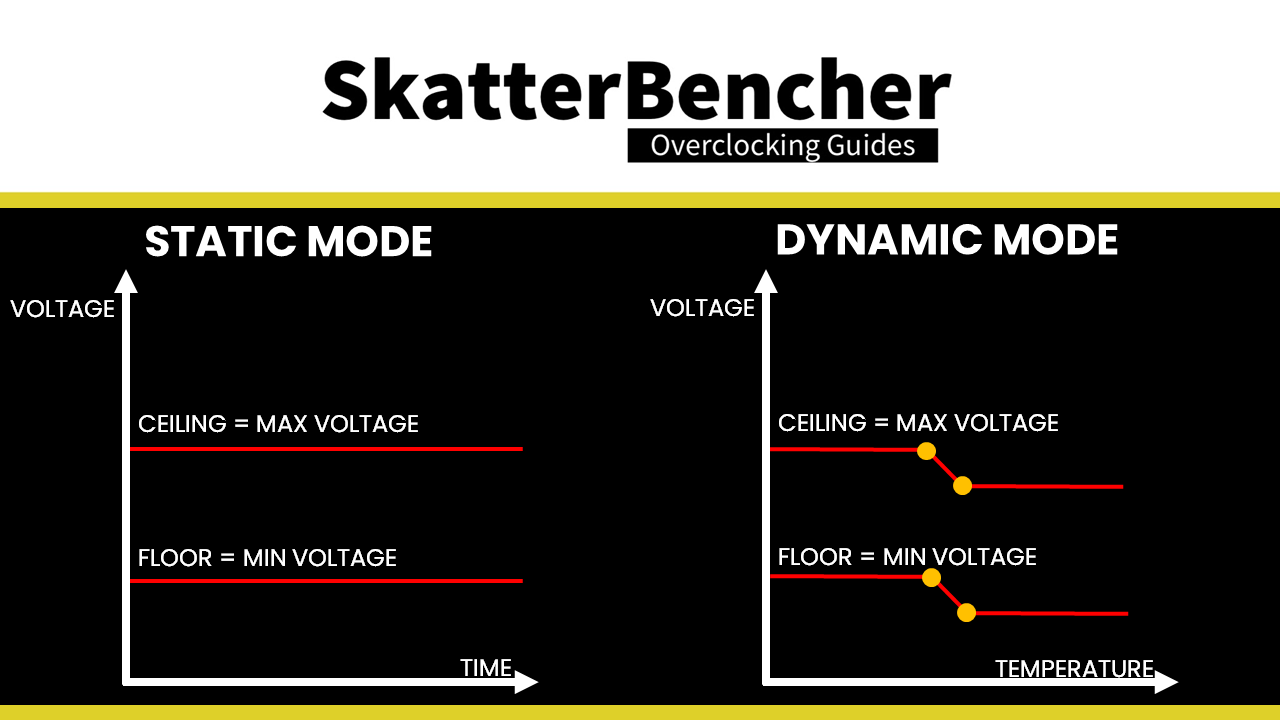
We can configure the Voltage Suspension by setting the voltage ceiling and voltage floor. Obviously, the ceiling is our maximum voltage and the floor is our minimum voltage. We can configure the ceiling and floor in static mode or dynamic mode.
In Static mode we set a maximum and minimum voltage and the Voltage Suspension function will try to keep the voltage between these two levels.
In Dynamic mode we kind of make our own voltage frequency curve, though we don’t use frequency as a parameter directly. Instead, we configure the ceiling and floor voltage as the function of four points defined by a voltage and temperature. So, I guess it’s more like a voltage temperature curve.
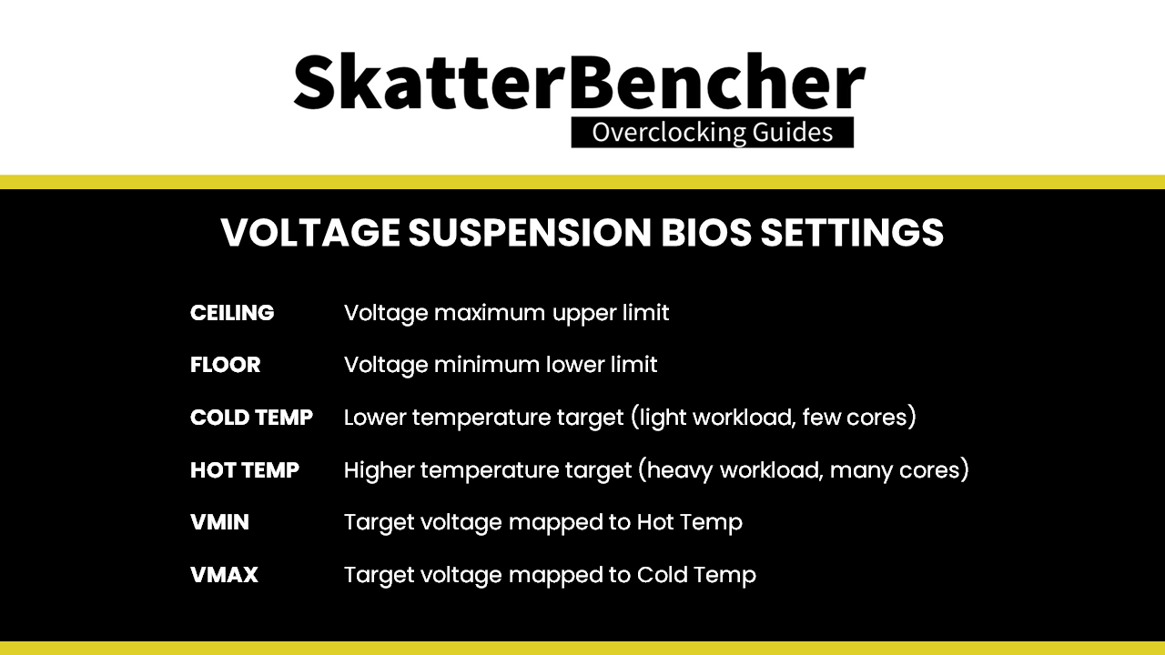
It gets a little complicated in the BIOS, but here’s what it boils down to:
- Ceiling values determine the maximum upper limit of the allowed voltage
- Floor values determine the minimum lower limit of the allowed voltage
- Cold Temp sets the lower temperature target; lower typically means light workloads with few cores active
- Hot Temp sets the upper temperature target; higher typically means heavy multi-threaded workloads with all cores active
- VMin voltages are mapped against Hot Temp targets
- VMax voltages are mapped against Cold Temp targets
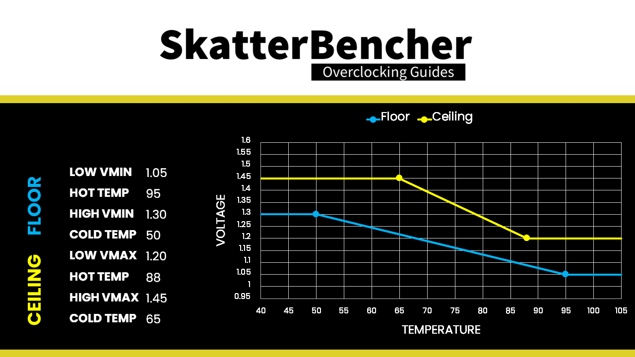
Maybe the best way to comprehend the feature is with an example. Let’s take the following parameters:
- Floor Low Vmin: 1.05
- Floor Hot Temp: 95
- Floor High Vmin: 1.30
- Floor Cold Temp: 50
- Ceiling Low Vmax: 1.20
- Ceiling Hot Temp: 88
- Ceiling High Vmax: 1.45
- Ceiling Cold Temp: 65
Now let’s put these parameters our voltage temperature curve with temperature on the x-axis and voltage on the y-axis. We mark our four points on the graph, then connect the two ceiling points and the two floor points. Now we have a linearly scaling curve for our voltage as function of the temperature.

Linear scaling means that the voltage suspension limits slide up and down the temperature scale. For example, if the temperature is 75 degrees Celsius, the voltage ceiling voltage will be about 1.35V and the voltage floor will be 1.15V.
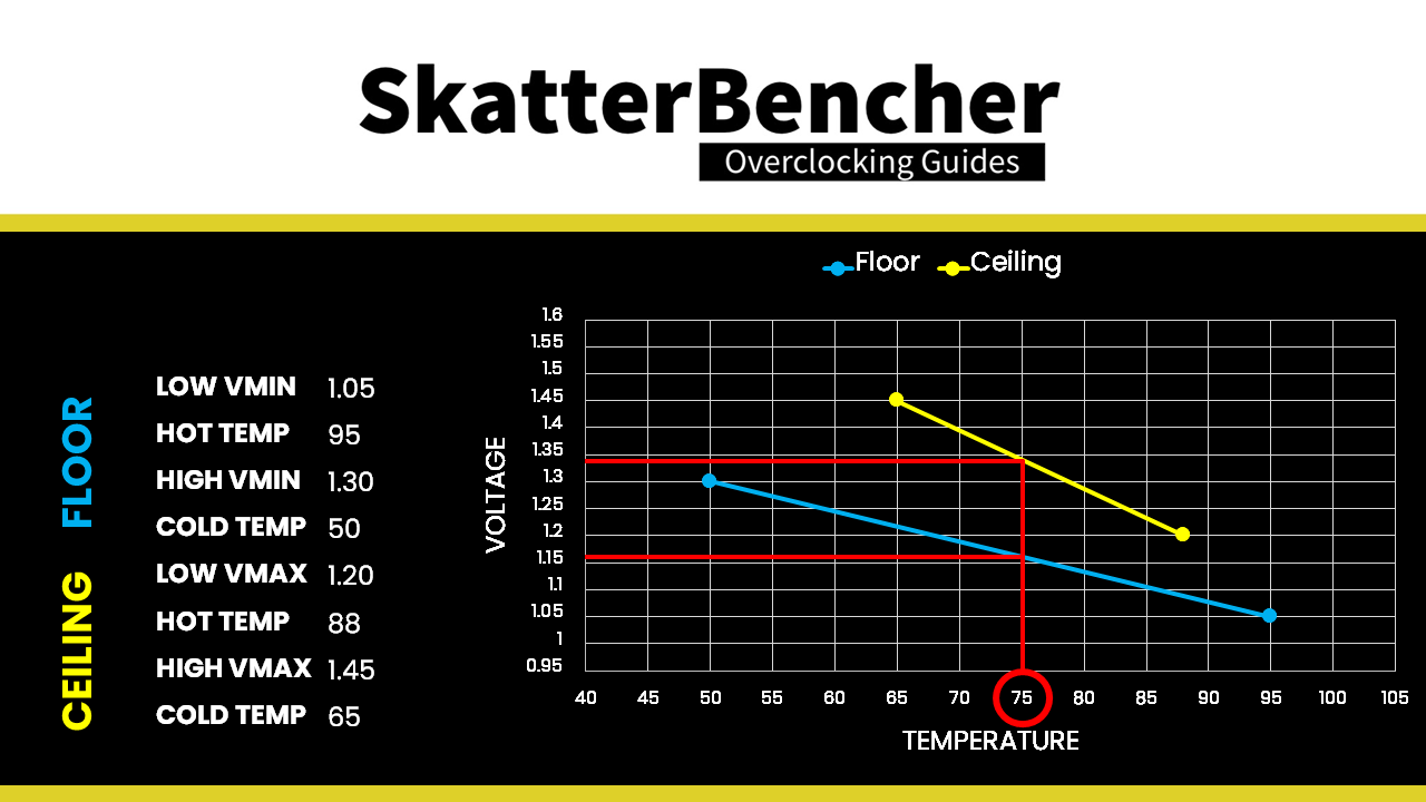
Note that the scaling does not continue linearly but the ceiling and floor are the upper and lower limit of the voltage target. So, 1.45V is the voltage ceiling at 65 degrees Celsius and below. And 1.20V is the voltage ceiling at 88 degrees Celsius and above. The same applies to the floor voltages.
Moving these four configurable points will alter the voltage temperature scaling according to your needs.
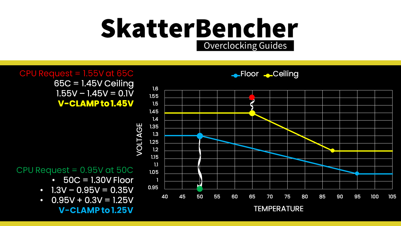
The V-Clamp is effective up to 0.3V difference between the requested voltage by the CPU and our configured voltage target. Returning to our example:
- At a temperature of 65 degrees Celsius the voltage ceiling is 1.45V. If the CPU requests 1.55V, then the voltage will be 1.45V as the difference between both values is less than 0.3V and our ceiling is 1.45V.
- At a temperature of 50 degrees Celsius the voltage floor is 1.3V. If the CPU requests 0.95V, then the voltage will be 1.25V as difference between floor voltage and requested CPU voltage is more than 0.3V. And, V-Clamp does not exceed 0.3V.
In addition to the ability to V-Clamp the Core Voltage, the Voltage Suspension also has a CO Mitigator feature.
Co mitigator aims to improve the Curve Optimization undervolting margins by boosting the voltage ever so slightly under very light loads. It does this by monitoring the current draw. When the current drops below a certain point, the voltage is boosted by 0.3V (yes, the maximum V-clamp). You can manually configure this point in the BIOS, though it is recommended to stick with the default of 0.3. This value isn’t voltage or amps, it’s just a unit to configure the co mitigator. Setting a higher value may cause the additional voltage to also be applied when there’s an actual light load and thus negatively impact your overclock.
Note that Voltage Suspension is still affected by the CPU VCore load-line and doesn’t affect any undershoot or overshoot. As a reminder: voltage suspension aims to adjust the request voltage by the CPU to stay within a pre-defined upper and lower limit. Any effect of the load-line occurs after this re-adjustment.
ASUS Voltage Suspension: Benefits & Applicability
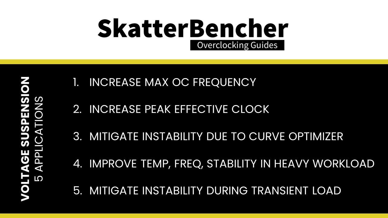
I found five situations where Voltage Suspension can be effective in helping you achieve higher performance when overclocking.
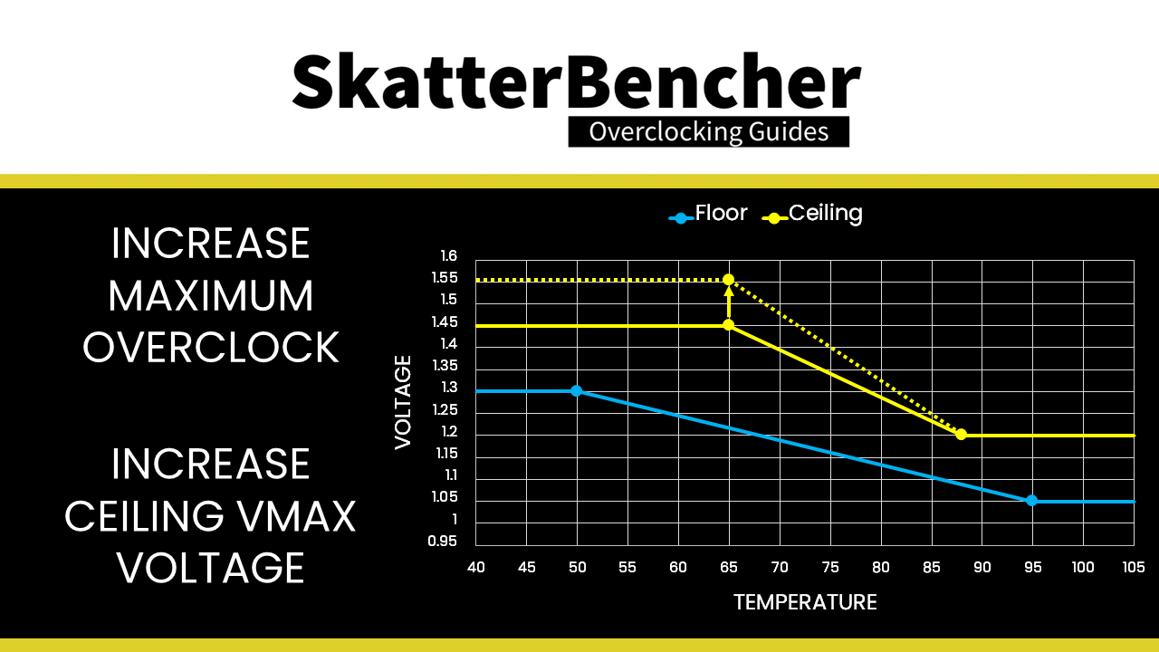
- Increase maximum overclocking frequency
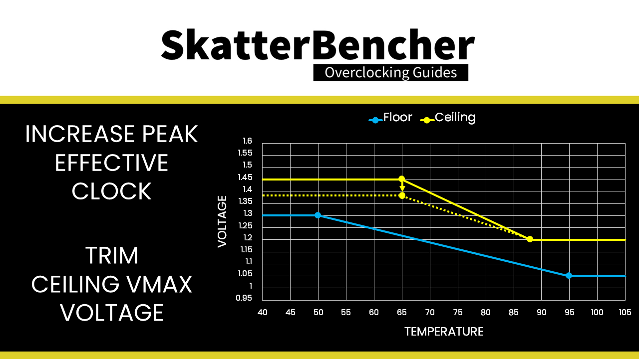
- Increase peak effective clock
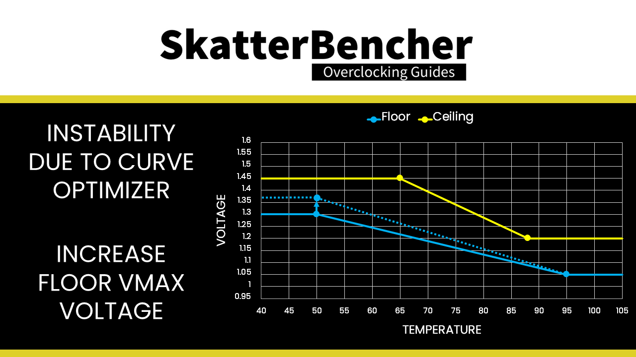
- Mitigate instability caused by aggressive Curve Optimizer settings
- Improve temperature, stability, and frequency for heavy multi-threaded workloads
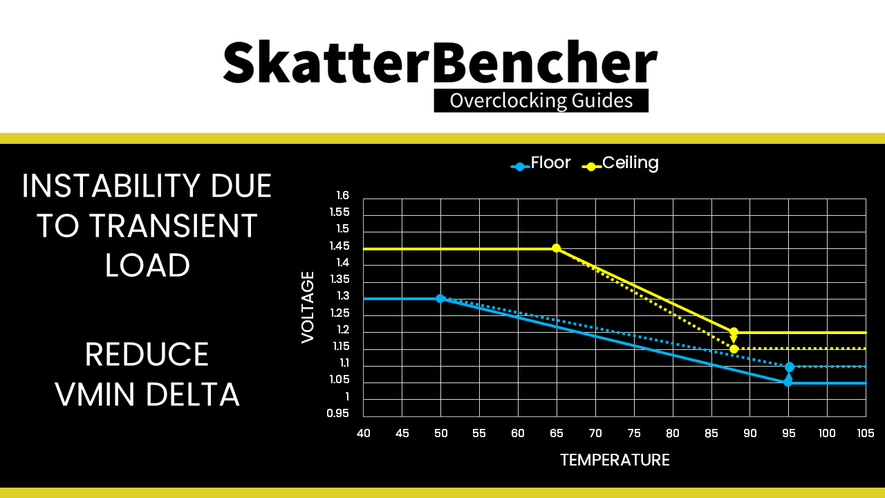
- Mitigate instability caused by rapid fluctuations from heavy all-core load to idle and back
First, the obvious one: when you increase the PBO frequency using the reference clock, you will need higher voltages to ensure stability. You can use a higher ceiling voltage to have a higher voltage than Precision Boost requests. This may help you stabilize the overclock.
Second, you can achieve slightly higher peak effective clock frequencies for light workloads by trimming the maximum voltage using the voltage ceiling. The starting point would be to check the peak voltage first, then lower it step by step using the dynamic ceiling Vmax. Capping the peak voltage with our manual ceiling may trigger the CPU to sense the voltage for a given frequency is too low and increase the requested VID which in turn could help push the frequency slightly higher. Of course, you must check carefully for clock stretching as trimming the voltage may cause instability. I was able to find scenarios where I could achieve about 20MHz higher peak effective clock in light workloads.
Third, you can use Voltage Suspension to mitigate instability when running aggressive Curve Optimizer settings. As you know, Curve Optimizer allows us to manipulate the voltage frequency curve of each of our CPU cores. By using a negative curve optimizer setting the Precision Boost algorithm will use less voltage for a given frequency. Or, of course, achieve a higher frequency for a given voltage.
However too low voltage will result in instability. There are two ways to mitigate instability due to too low voltage as a result of aggressive use of curve optimizer.
- Use the CO mitigator to boost the voltage ever so slightly under very light loads.
- Configure the floor Vmax such that at light loads the voltage would not drop below a certain level.
The fourth application of Voltage Suspension is the one I found most useful. Namely mitigating the effects of using a voltage offset on heavy workload stability. As you’ve seen from our PBO Supercharged overclocking strategy, when adding a voltage offset the Prime95 SmallFFTs with AVX enabled workload was no longer stable. But as you’ll see later on, with Voltage Suspension I was not only able to get the system stable but also lower the operating temperatures significantly.

Lastly, you can use Voltage Suspension to mitigate the effects of a transient load. In some situations, you may find that the workload is switching between full load and no load rapidly. The difference in load and the effect it has on the effective voltage could result in an unstable system. By setting an appropriate voltage floor, you can try to mitigate this issue.
ASUS Voltage Suspension: Setting Up Your System
Now comes the part where I’d like to provide you with a step-by-step guide on how to set up the Voltage Suspension configuration. However, truth be told … I don’t have a solid procedure yet. So rather than pretending I do, I’ll share my configuration from SkatterBencher #29 and give you some context how I approached the configuration.
I’m sure that as more experienced enthusiasts and overclockers get their hands on this feature, better approaches will surface. So, I’d love to hear from you how you set up Voltage Suspension on your system.
Here are my Voltage Suspension settings:
- Floor Low Vmin: 1.15
- Floor Hot Temp: 90
- Floor High Vmin: 1.40
- Floor Cold Temp: 60
- Ceiling Low Vmax: 1.20
- Ceiling Hot Temp: 85
- Ceiling High Vmax: 1.53125
- Ceiling Cold Temp: 65
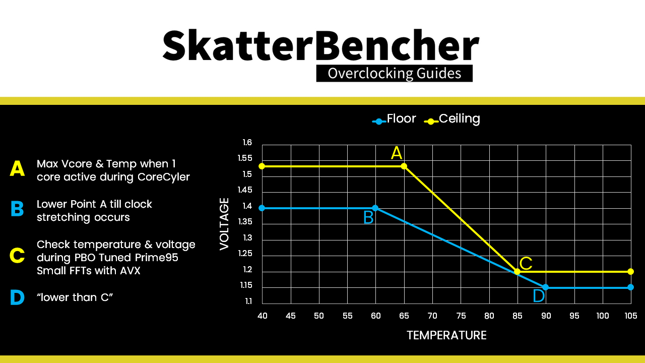
Let’s put them in a chart and label the points A, B, C, and D. With,
- A = ceiling high
- B = floor high
- C = ceiling low
- D = floor low

To set point A, I checked the Vcore and temperature when one core is loaded during CoreCycler. I tried to find the lowest voltage needed to achieve the highest stable peak effective clock frequency for all cores.
To set point B, I tried lowering point A in voltage until I saw clock stretching occur.
To set point C, I relied on the information from OC Strategy #2 where we tuned PBO. When running Prime 95 Small FFTs with AVX enabled, the average effective CPU clock was 4234 MHz with 1.187 volts and the average CPU temperature is 86 degrees Celsius. So my aim was to limit the maximum voltage to 1.2 at a temperature of around 85 degrees Celsius.
To set point D, I … kinda just put it slightly lower than point C.
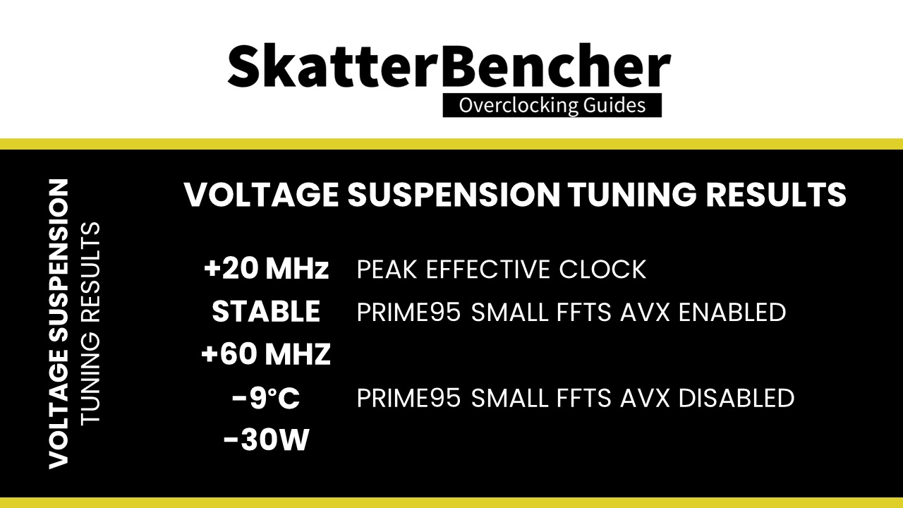
In terms of additional peak frequency, we didn’t gain much over our PBO Supercharged OC strategy. However, for our all-core workloads the results are much more impressive. Not only did we manage to get a stable system for Prime95 Small FFTs with AVX enabled, we also achieved 60MHz higher frequency at 9 degrees Celsius lower temperature. The average CPU Package Power is almost 30W lower too!
In fact, the temperature improvement was so good that our Prime95 Small FFTs with AVX enabled was not only stable but also hitting too high frequency for 1.2V. To limit the frequency I had to lower the PPT limit to 205 which resulted in a stable frequency.
ASUS Voltage Suspension in SkatterBencher Guides
We use ASUS Voltage Suspension in the following SkatterBencher guides: