AMD Precision Boost 2 opportunistically increases the CPU performance based on the CPU temperature, current, and power headroom.

AMD detailed how Precision Boost worked on the first-generation Zen in a 2018 paper titled “Zeppelin”: An SoC for Multichip Architectures.
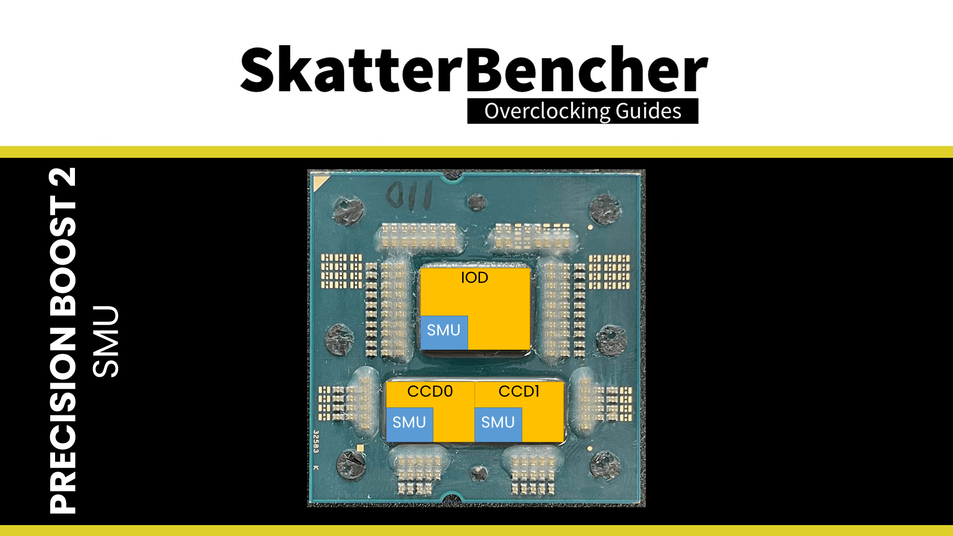
SMU – System Management Unit
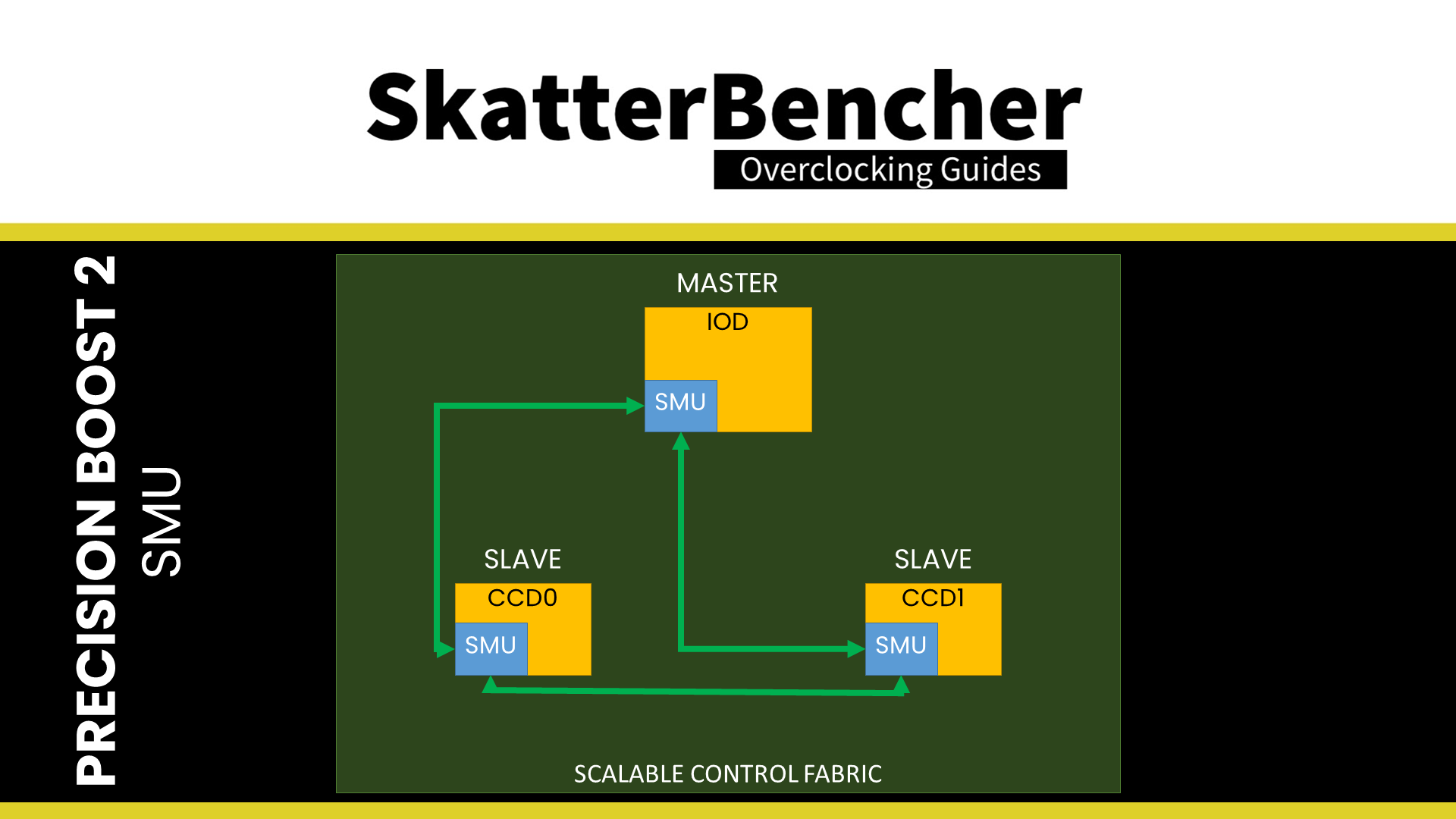
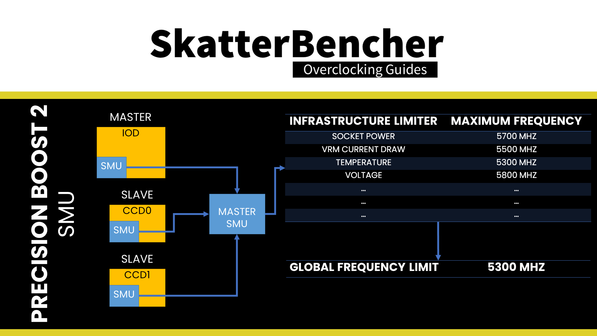
The Precision Boost 2 magic is performed by the SMU. SMU is short for System Management Unit. Each chip on your Raphael CPU has an SMU, meaning there are 3 SMUs on a Raphael CPU with 2 CCDs and 1 IOD. One of those SMUs will work as Master SMU, while the others work as Slave SMUs. Typically, the SMU in the IO die would be the Master SMU. All SMUs are connected using a low-bandwidth control bus called SCF or Scalable Control Fabric.
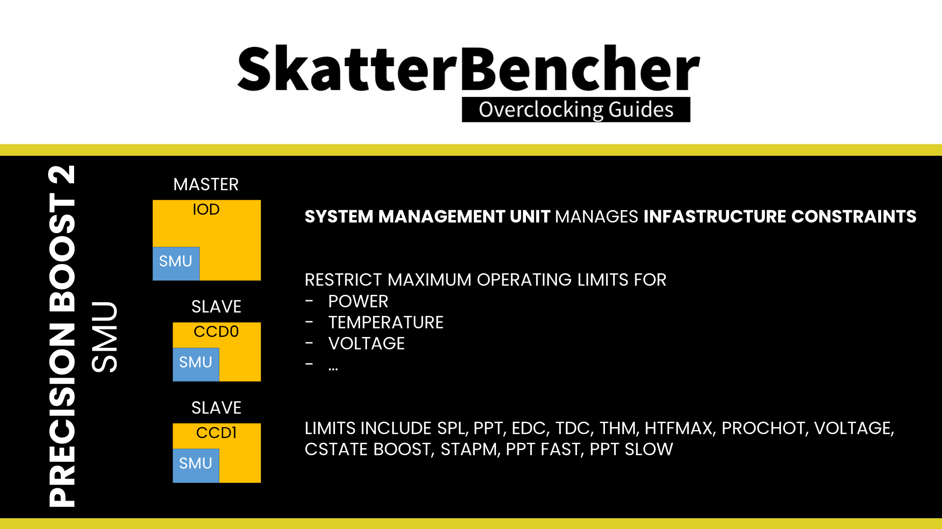
The SMU has a range of capabilities, including, most importantly, the ability to manage the CPU performance within the infrastructure constraints. The infrastructure restricts the maximum operating limits on various metrics, including power draw, temperature, and voltage. We don’t have a comprehensive, confirmed list of metrics, though some are exposed to the end-user. On Raphael, the exposed infrastructure limits include the following: SPL, PPT, EDC, TDC, THM, HTFMax, ProcHot, Voltage, CState Boost, STAPM, PPT Fast, and PPT Slow. We’ll have a closer look at each of these in a minute.
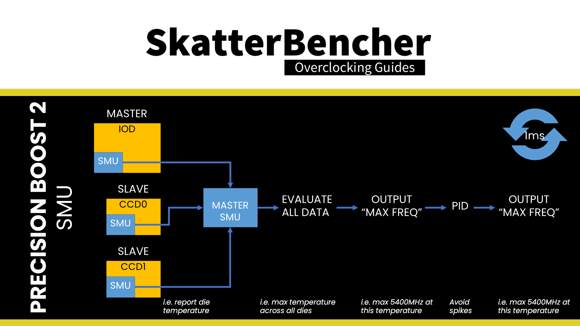
The primary function of the slave SMUs is to capture the measurement data related to the infrastructure limits, then prepare that data to be sent to the master SMU. The master SMU’s primary function is to analyze the package-wide measurement data and determine the actions needed for performance management.
Each infrastructure limit has its own algorithm and is managed independently by the master SMU to determine the infrastructure limited frequency. The process for each algorithm is as follows:
- Receive data from the slave SMUs
- Aggregate the data into a single evaluation, with the output being the maximum frequency limit for a given infrastructure algorithm
- Input the result to a PID (proportional-integral-differential) controller, which smoothens out the responses over a longer period and avoids spikes or quick changes
- The changing output of the PID controller is the maximum frequency allowed by a specific infrastructure limit at a given time.
This process is repeated approximately every 1 millisecond for each algorithm.
The firmware then selects the most constraining limit as the global frequency limit.
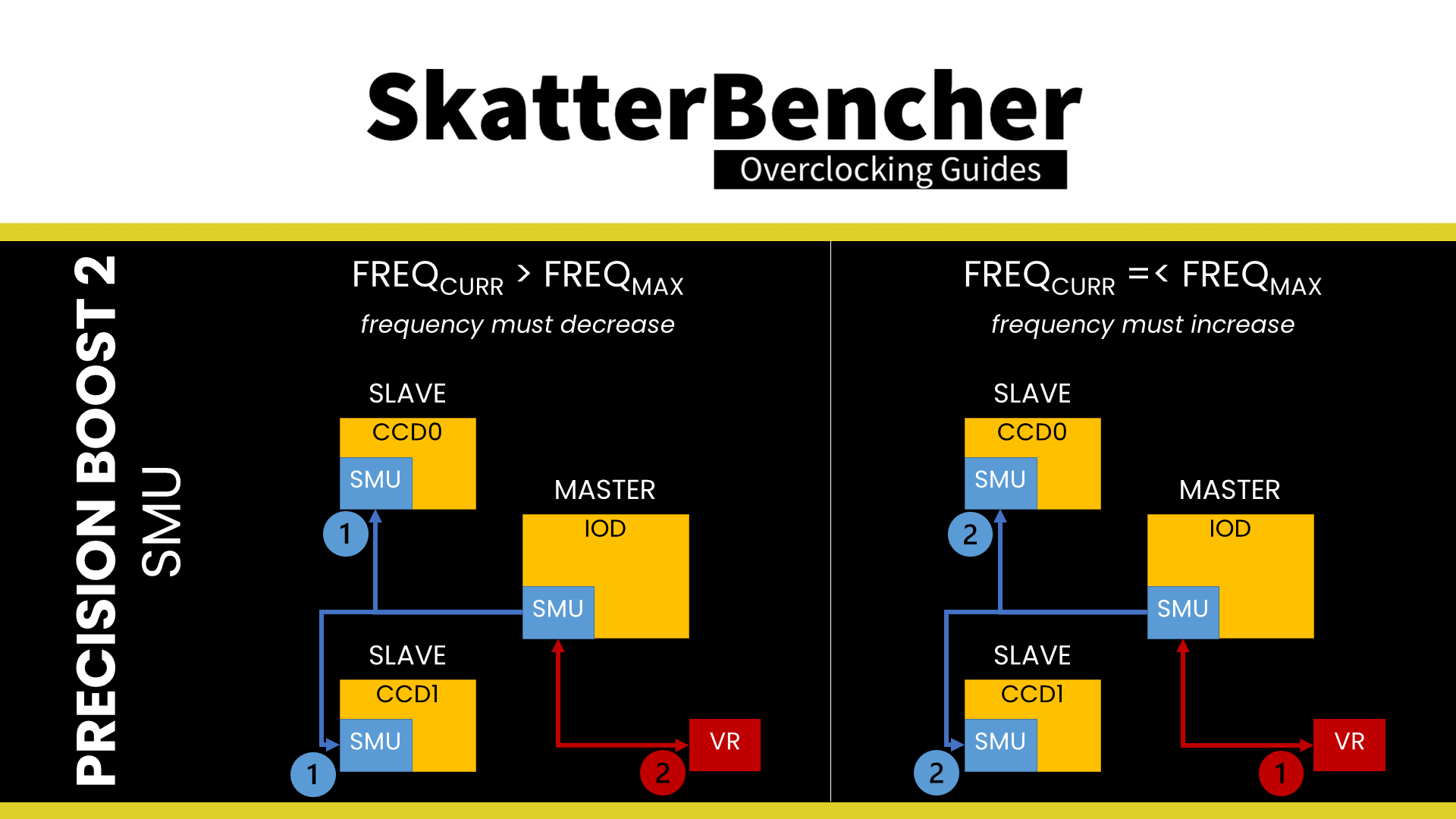
Then, either of two things can happen: the current frequency exceeds the limit, or it doesn’t. If it does, the frequency is reduced. If it doesn’t, there’s frequency headroom, and the frequency will increase.
Either way, the master SMU passes the frequency change request to the slave, and each slave applies the frequency changes to the CPU cores of the local die. The frequency changes are coordinated with the global voltage plane by the master SMU.
If the frequency increases, the master first sends a VID voltage command to the external voltage regulator before sending frequency increase commands to the slave SMUs.
If the frequency decreases, the master first sends the frequency change request to the slaves. Then it waits for the frequency change to be acknowledged. Lastly, it sends the VID voltage command to the voltage regulator.
The slave SMUs can make independent decisions based on local conditions. So, it can apply lower frequencies than the frequency requested by the master SMU if the on-die conditions require so. For example, one CCX may run a lower frequency in all-core workloads than the other. Additionally, when dLDO is enabled, each SMU can independently adjust the voltage for each core within the CCX.
Precision Boost 2 Infrastructure Limiters
Now, let’s have a closer look at the Precision Boost 2 infrastructure limiters exposed to the end-user. While all these limiters are present on a Ryzen 7000 CPU, it doesn’t mean they’re all active or configured. Some limiters are not relevant to a desktop system and may be ignored.
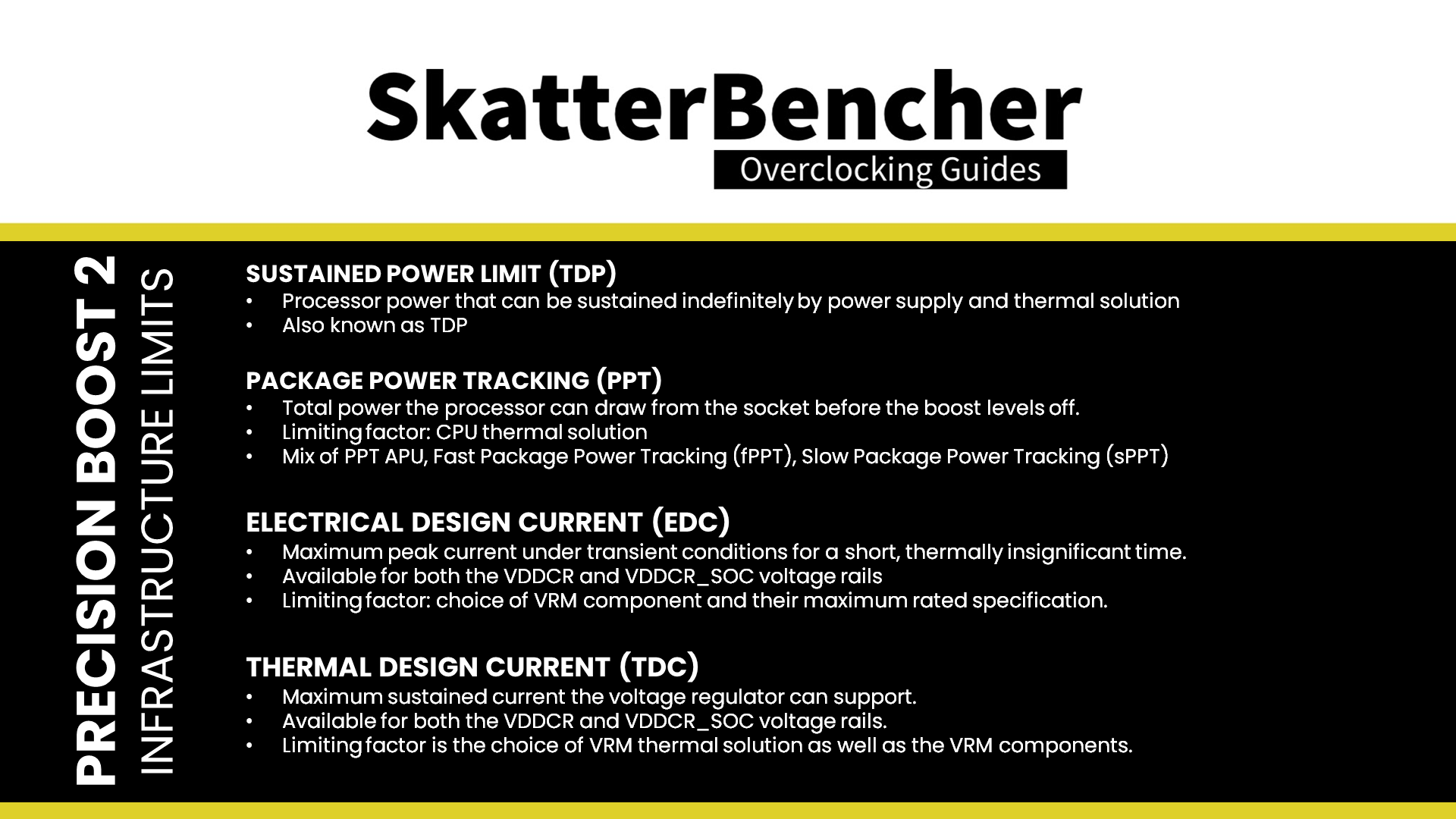
- Sustained Power Limit, or SPL, is the processor power that can be sustained indefinitely by the power supply and thermal solution. It’s also known as the TDP.
- Package Power Tracking, or PPT, is the total power the processor can draw from the socket before the boost levels off. Typically, the limiting factor is your CPU thermal solution. In technical documentation, you’ll find that PPT is actually a combination of three power-related options: PPT APU (PPT), Fast Package Power Tracking (fPPT), and Slow Package Power Tracking (sPPT). Depending on your platform, some of these parameters may not be used. For desktop Raphael, Fast PPT is the parameter we override when configuring PPT.
- Electrical Design Current, or EDC, represents the maximum peak current the voltage rail can demand under transient conditions for a short, thermally insignificant time. Independent EDC tuning is available for both the VDDCR and VDDCR_SOC voltage rails. Typically, the limiting factor is the choice of VRM components and their maximum rated specification.
- Thermal Design Current, or TDC, represents the maximum sustained current the voltage regulator can support. Independent TDC tuning is available for both the VDDCR and VDDCR_SOC voltage rails. Typically, the limiting factor is the choice of VRM thermal solution and the VRM components.
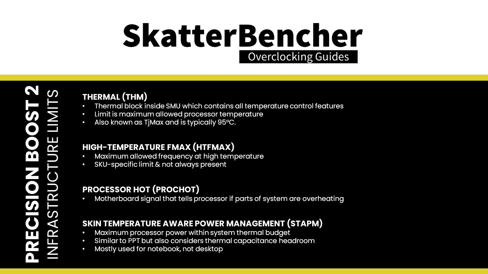
- Thermal, or THM, represents the thermal block inside the SMU that contains all temperature sensors, control, and reporting features. The THM limit is the maximum allowed processor operating temperature and is commonly known as TjMax.
- High-temperature Fmax, or HTFMax, represents the maximum frequency allowed at high operating temperatures. This limiter is SKU-specific and may or may not be present. For example, on the 7600X, the HTFmax limiter starts at 5450 MHz at 70 degrees Celsius. The frequency reduces linearly until it reaches 5150 MHz at 95 degrees Celsius. However, on the 7900X, this limiter does not appear to be present.
- Processor Hot, or PROCHOT, is a signal within the motherboard design that tells the processor other system elements are overheating and allows the processor to throttle performance.
- Skin Temperature Aware Power Management, or STAPM, represents the maximum power the processor can use within the thermal budget of the whole system. It is similar to the package power but also considers the system thermal capacitance headroom. It is primarily relevant for notebooks, not so much for desktop.
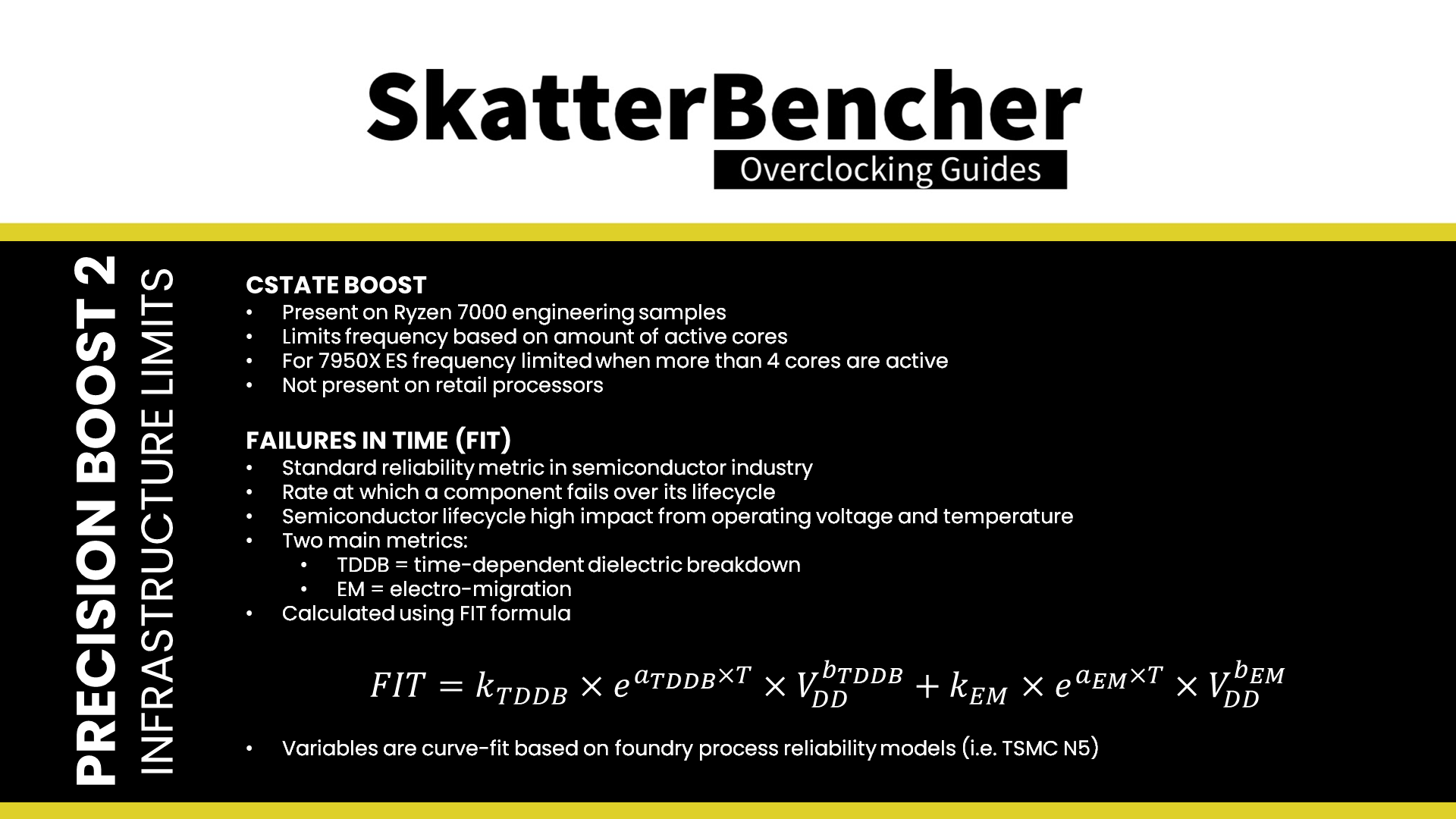
- CState Boost is a specific boost limiter present on early engineering samples. Effectively, C-State Boost limits the maximum frequency when a certain number of active cores is exceeded. For the 16-core 7950X, the C-State Boost limit would force the CPU to run at 5.2 GHz when more than four cores are active.
This Precision Boost 2 limiter is not active on retail processors.The CState Boost limit was re-introduced with retail products on AGESA 1003. - Failures in Time, or FIT, is a standard reliability engineering metric used in the semiconductor industry. It represents the rate at which a component fails over its life cycle. For semiconductors, operating voltage and temperature are the most relevant factors for failure. AMD’s real-time reliability monitoring technology incorporates two critical limiters to long-term reliability in a high-performance microprocessor: time-dependent dielectric breakdown, TDDB, and electromigration, or EM. The FIT rate is calculated in a 1-millisecond interval using the following formula. Where the subscripted variables are curve-fit based on the foundry process reliability models. So, for Raphael, that’s based on the reliability models provided by TSMC. The calculated FIT rate then passes through a filter to ensure smoother transitions preventing the frequency from changing too quickly.In short, if the FIT rate is below the target threshold, then there’s additional frequency headroom. Suppose the FIT rate is above the target threshold. In that case, the frequency headroom is lowered to prevent any early processor failure during the product lifecycle.
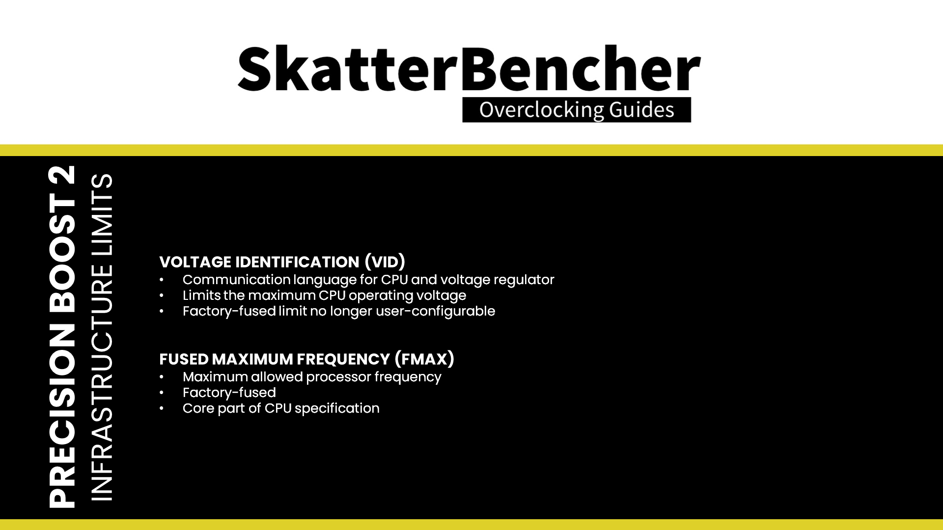
- Voltage Identification, or VID, is a way for the CPU and voltage controller to communicate voltage requests. The VID limit is the maximum allowed voltage for the processor. The VID limit is factory-fused and cannot be changed by the end-user (anymore).
- Fused maximum frequency, or Fmax, is the maximum allowed processor frequency. This value is fused from the factory and is obviously a core part of the CPU specification.