SkatterBencher #50: Intel Core i7-13700K Overclocked to 6000MHz

We overclock the Intel Core i7-13700K up to 6000 MHz with the EK-Mana MSI MAG Z690 Torpedo EK X motherboard and EK custom loop water cooling.
Raptor Lake processors provide a lot of room for performance tuning and overclocking, especially when paired with water cooling. By using a low-end Z690 motherboard, I hope to illustrate that this previous-generation platform can still push Raptor Lake to its limits.
That said, tuning Raptor Lake doesn’t come without its own challenges. I will do my best to explain how it works, and I hope you enjoy the blog post.
Intel Core i7-13700K: Introduction
The Intel Core i7-13700K is part of the 13th generation Intel Core processor lineup.
Intel Raptor Lake builds on top of the performance hybrid architecture introduced with 12th gen Alder Lake. So, it also features Performance P-Cores and Efficient E-cores. Like Alder Lake, it is built on the Intel 7 process technology, formerly known as 10nm Enhanced SuperFin (ESF). While it may sound like Raptor Like is not much different from its predecessor, the spec sheet reads quite impressive.
Compared to its Core i7-12700K predecessor, launched one year ago, the 13700K has a 400 MHz higher turbo boost frequency and four additional threads while costing $40 less.

In this article, we will cover four different overclocking strategies:
- First, we unleash the Turbo Boost limits and enable XMP 3.0
- Second, we overclock using MSI Game Boost technology
- Third, we overclock using MSI’s Turbo Ratio Offset feature
- Lastly, we get into the manual tuning of a Raptor Lake processor

However, before we jump into overclocking, let us quickly review the hardware and benchmarks used in this overclocking guide.
Intel Core i7-13700K: Platform Overview
The system we’re overclocking today consists of the following hardware.
| Item | SKU | Price (USD) |
| CPU | Intel Core i7-13700K | 440 |
| Motherboard | EK-Mana MSI MAG Z690 Torpedo EK X | 295 |
| CPU Cooling | EK-Pro QDC Kit P360 | 777 |
| Fan Controller | ElmorLabs Easy Fan Controller ElmorLabs EVC2SX | 20 32 |
| Memory | Aorus DDR5-6200 | 250 |
| Power Supply | Antec HCP 1000W Platinum | 110 |
| Graphics Card | ASUS ROG Strix RTX 2080 TI | 880 |
| Storage | Kingston SSDNow KC400 512GB SSD | 240 |
| Chassis | Open Benchtable V2 | 200 |
ElmorLabs EFC & EVC2
I explained how I use ElmorLabs products in SkatterBencher #34. By connecting the EFC to the EVC2 device, I monitor the ambient temperature (EFC), water temperature (EFC), and fan duty cycle (EFC). I include the measurements in my Prime95 stability test results.
I also use the ElmorLabs EFC to map the radiator fan curve to the water temperature. Without going into too many details: I have attached an external temperature sensor from the water in the loop to the EFC. Then, I use the low/high setting to map the fan curve from 25 to 40 degrees water temperature. I use this configuration for all overclocking strategies.
The main takeaway from this configuration is that it gives us a good indicator of whether the cooling solution is saturated.
Suppose the CPU is at TjMax, and the water temperature exceeds 40 degrees Celsius. In that case, it means the fans are at maximum speed, and thus the cooling solution is saturated. Improving the cooling solution by adding radiators or changing to more powerful fans would be the right action.

Suppose the CPU is at TjMax and the water temperature is below 40 degrees Celsius. In that case, it means the cooling solution is not saturated. Therefore, to improve the CPU temperature, you may enhance the thermal transfer of the CPU heat into the loop by changing the thermal paste, delidding, or changing the water block.

EK-Mana MSI MPG Z690 Torpedo EK X
The Z690 Torpedo EK X is the fifth collaborative motherboard from EK and MSI, following the Carbon EK X for Z490, Z590, X570, and Z690. However, it is the first motherboard that introduces the concept of the EK-LiteBlock. I already covered the LiteBlock design characteristics at length in SkatterBencher #34, but let’s quickly go over the main points.
The EK-LiteBlock sits between a regular CPU water block and a monoblock. It’s not a monoblock because it doesn’t directly cool the VRM of the motherboard, and it’s also not quite a CPU block because it still indirectly cools the VRM. So how does it work?
MSI redesigned the Z690 Torpedo VRM heatsink to feature a flat surface on both the West and North side of the heatsink. The EK LiteBlock then extends from the CPU socket over the VRM heatsink flat surface and, with the help of two thermal pads, makes contact with the VRM heatsink. The result is that even though it’s not a monoblock, the LiteBlock still actively cools the VRM.

If you want to learn more, I suggest you check the EK or MSI product page.
Intel Core i7-13700K: Benchmark Software
We use Windows 11 and the following benchmark applications to measure performance and ensure system stability.
- SuperPI 4M https://www.techpowerup.com/download/super-pi/
- Geekbench 5 https://www.geekbench.com/
- Cinebench R23 https://www.maxon.net/en/cinebench/
- CPU-Z https://www.cpuid.com/softwares/cpu-z.html
- V-Ray 5 https://www.chaosgroup.com/vray/benchmark
- AI-Benchmark https://ai-benchmark.com/
- 3DMark CPU Profile https://www.3dmark.com/
- 3DMark Night Raid https://www.3dmark.com/
- CS:GO FPS Bench https://steamcommunity.com/sharedfiles/filedetails/?id=500334237
- Shadow of the Tomb Raider https://store.steampowered.com/app/750920/Shadow_of_the_Tomb_Raider_Definitive_Edition/
- Final Fantasy XV http://benchmark.finalfantasyxv.com/na/
- Prime 95 https://www.mersenne.org/download/

Intel Core i7-13700K: Stock Performance
Before starting overclocking, we must check the system performance at default settings.
Please note that out of the box, the EK-Mana MSI MAG Z690 Torpedo EK X fully unleashes the Turbo Boost 2.0 power limits. So, to check the performance at default settings, you must
- In Advanced Mode
- Enter the Overclocking settings menu
- Ensure CPU Cooler Tuning is set to Boxed Cooler (PL1: 253W)
Then save and exit the BIOS.
The default Turbo Boost parameters for the Core i7-13700K are as follows:
- PL1: 253W
- PL2: 253W
- Tau: 56sec
- ICCMax: 280A

Here is the benchmark performance at stock:
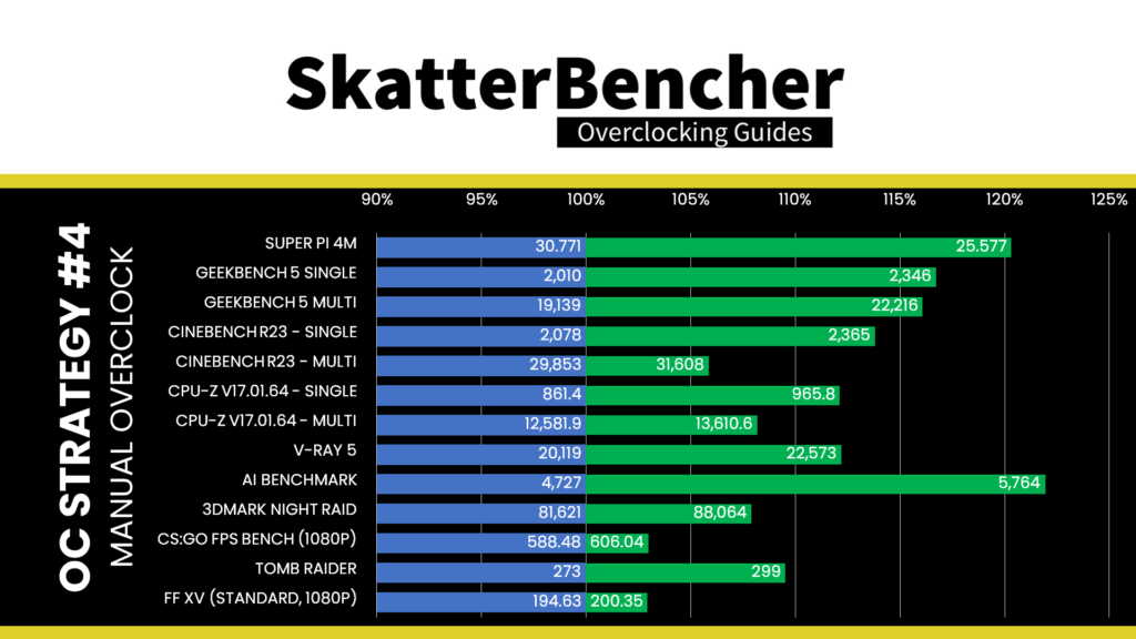
- SuperPI 4M: 30.771 seconds
- Geekbench 5 (single): 2,010 points
- Geekbench 5 (multi): 19,139 points
- Cinebench R23 Single: 2,078 points
- Cinebench R23 Multi: 29,583 points
- CPU-Z V17.01.64 Single: 861.4 points
- CPU-Z V17.01.64 Multi: 12,581.9 points
- V-Ray 5: 20,119 vsamples
- AI Benchmark: 4,727 points
- 3DMark Night Raid: 81,621 points
- CS:GO FPS Bench: 588.48 fps
- Tom Raider: 273 fps
- Final Fantasy XV: 194.63 fps

Here are the 3DMark CPU Profile scores at stock
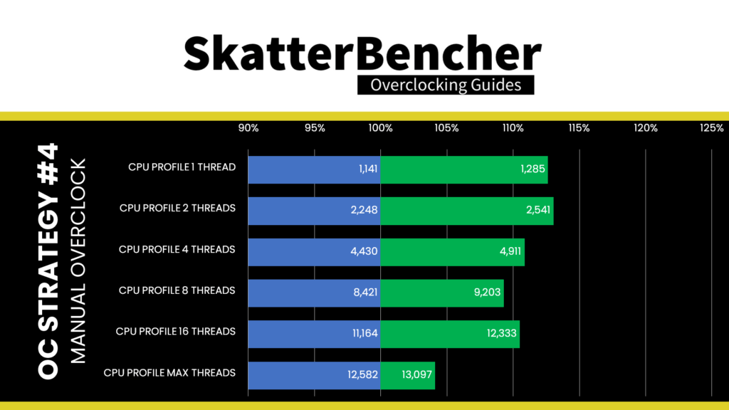
- CPU Profile 1 Thread: 1,141
- CPU Profile 2 Threads: 2,248
- CPU Profile 4 Threads: 4,430
- CPU Profile 8 Threads: 8,421
- CPU Profile 16 Threads: 11,164
- CPU Profile Max Threads: 12,582

When running Prime 95 Small FFTs with AVX2 enabled, the average CPU P-core clock is 4975 MHz and average CPU E-core clock is 3801 MHz with 1.141 volts. The average CPU temperature is 90 degrees Celsius. The ambient and water temperature is 26.2 and 37.4 degrees Celsius. The average CPU package power is 253.0 watts.

When running Prime 95 Small FFTs with AVX disabled, the average CPU P-core clock is 5225 MHz and average CPU E-core clock is 4091 MHz with 1.222 volts. The average CPU temperature is 90 degrees Celsius. The ambient and water temperature is 26.0 and 37.4 degrees Celsius. The average CPU package power is 253.0 watts.

Now, let us try our first overclocking strategy.
However, before we get going, make sure to locate the CMOS Clear pins
Shorting the Clear CMOS pins will reset all your BIOS settings to default which is helpful if you want to start your BIOS configuration from scratch. However, it does not delete any of the BIOS profiles previously saved. The Clear CMOS pins are located in the bottom left of the motherboard.

OC Strategy #1: Unleashed Turbo + XMP 3.0
In our first overclocking strategy, we take advantage of unleashing the Turbo Boost 2.0 power limits and Intel XMP 3.0.
Intel Turbo Boost 2.0
Intel Turbo Boost 2.0 Technology allows the processor cores to run faster than the base operating frequency. Turbo Boost is available when the processor works below its rated power, temperature, and current specification limits. The ultimate advantage is opportunistic performance improvements in both multi-threaded and single-threaded workloads.
The turbo boost algorithm works according to a proprietary EWMA formula. This stands for Exponentially Weighted Moving Average. There are 3 parameters to consider: PL1, PL2, and Tau.
- Power Limit 1, or PL1, is the threshold the average power will not exceed. Historically, this has always been set equal to Intel’s advertised TDP. PL1 should not be set higher than the thermal solution cooling limits.
- Power Limit 2, or PL2, is the maximum power the processor can use for a limited amount of time.
- Tau, in seconds, is the time window for calculating the average power consumption. The CPU will reduce the CPU frequency if the average power consumed is higher than PL1.

Turbo Boost 2.0 technology is available on Raptor Lake as it’s the primary driver of performance over the base frequency.
Similar to Alder Lake, but a significant change from any previous Intel Core processors is that, at least for the K-SKU CPUs, PL1 is by default equal to PL2. This differs from before, where PL1 would equal the TDP, and PL2 would range from 200 to 250W. This change effectively means that Intel has enabled near-unlimited peak turbo by default!

For the 13700K, the maximum power limit is set at 253W.
The maximum performance is, therefore, entirely limited by the capabilities of your cooling solution. If your cooling solution is insufficient, the processor will reduce the operating frequency at the maximum allowed temperature or TjMax. For Raptor Lake CPUs, that’s at 100 degrees Celsius.
An easy CPU Cooler Tuning option on MSI motherboards allows you to unleash the Turbo Boost power limits. Set the option to Water Cooler and enjoy the maximum performance. The BIOS will give a menu on the first boot to select the CPU cooler type. On the Z690 Torpedo EK X, Water Cooler and its associated unlocked Turbo Boost power limits is set.

Adjusting the power limits is strictly not considered overclocking, as we don’t change any of the CPU’s thermal, electrical, or frequency parameters. Intel provides the Turbo Boost parameters as guidance to motherboard vendors and system integrators to ensure their designs enable the base performance of the CPU. Better motherboard designs, thermal solutions, and system configurations can facilitate peak performance for longer.
Intel Turbo Boost Max 3.0
Note that there’s also an Intel technology called Turbo Boost Max 3.0. While the technologies carry the same name, they are not the same.
Turbo Boost 2.0 focuses explicitly on exploiting the available power budget to provide additional computing performance. On the other hand, Turbo Boost Max Technology 3.0 aims to use the natural variance in CPU core quality observed in multi-core CPUs. With Turbo Boost Max 3.0, Intel identifies the best cores in your CPU and calls those the favored cores.

The favored cores are essential for two reasons.
- First, Intel allows for additional frequency boosts of the favored cores. On the 13700K, there are two favored P-cores and no favored E-cores. Both favored P-cores can boost to 5.4 GHz, while the other 6 P-cores can only boost up to 5.3 GHz. Note that the 5.4 GHz is restricted to only scenarios where 2 core is active.
- Second, the operating system will automatically assign the most demanding workloads to these favored cores, ensuring potentially higher performance.

The performance benefit of ITBMT 3.0 is most visible in low thread count workloads. Highly threaded workloads do not benefit from ITBMT 3.0.
Intel Extreme Memory Profile 3.0
Intel Extreme Memory Profile, or XMP, is an Intel technology that lets you automatically overclock the system memory to improve system performance. It extends the standard JEDEC specification and allows a memory vendor to program different settings onto the memory stick.
Intel Extreme Memory Profile 3.0 is the new XMP standard for DDR5 memory. It is primarily based on the XMP 2.0 standard for DDR4 but has additional functionality.

The XMP 3.0 standard is designed with six sections. One global section describes the generic data which is used across the profiles. The other five sections are designed for five profiles, respectively.
- Profile 1 is meant for the performance profile (this is the standard XMP as we know it)
- Profile 2 is designed for extreme settings (this could be a higher frequency at higher voltage)
- Profile 3 is designed for the fastest settings (this could be tighter timings at higher voltage)
- Profiles 4 and 5 are rewritable and meant for user custom settings

There’s a lot more to the new XMP 3.0 standard, which is outside the scope of this overclocking guide. If you’re interested in more details about XMP 3.0, feel free to check out my Alder Lake launch article.
BIOS Settings & Benchmark Results
Upon entering the BIOS
- In Advanced Mode, click XMP Profile 1
- Enter the Overclocking settings menu
- Ensure CPU Cooler Tuning is set to Water Cooler (PL1: 4096W)
Then save and exit the BIOS.
We re-ran the benchmarks and checked the performance increase compared to the default operation.
- SuperPI 4M: +0.50%
- Geekbench 5 (single): +2.24%
- Geekbench 5 (multi): +8.06%
- Cinebench R23 Single: +0.43%
- Cinebench R23 Multi: +2.24%
- CPU-Z V17.01.64 Single: +0.58%
- CPU-Z V17.01.64 Multi: +0.18%
- V-Ray 5: +3.92%
- AI Benchmark: +7.09%
- 3DMark Night Raid: +0.90%
- CS:GO FPS Bench: +1.44%
- Tomb Raider: +4.40%
- Final Fantasy XV: +0.48%

Here are the 3DMark CPU Profile scores at stock
- CPU Profile 1 Thread: +0.18%
- CPU Profile 2 Threads: +0.27%
- CPU Profile 4 Threads: +0.45%
- CPU Profile 8 Threads: +0.45%
- CPU Profile 16 Threads: +1.54%
- CPU Profile Max Threads: +2.11%

As expected, since we’re not increasing the frequency of the 13700K CPU cores, the performance improvement is relatively limited. That said, improving the memory performance by using XMP 3.0 does help in memory-sensitive benchmark applications. We see the highest performance improvement of +8.06% in Geekbench 5.
When running Prime 95 Small FFTs with AVX2 enabled, the average CPU P-core clock is 5090 MHz and average CPU E-core clock is 4076 MHz with 1.188 volts. The average CPU temperature is 100 degrees Celsius. The ambient and water temperature is 26.7 and 38.3 degrees Celsius. The average CPU package power is 288.9 watts.

When running Prime 95 Small FFTs with AVX disabled, the average CPU P-core clock is 5287 MHz and average CPU E-core clock is 4190 MHz with 1.237 volts. The average CPU temperature is 95 degrees Celsius. The ambient and water temperature is 26.5 and 37.8 degrees Celsius. The average CPU package power is 268.2 watts.

OC Strategy #2: Game Boost + XMP 3.0
In our second overclocking strategy, we use the one-click overclocking feature called Game Boost. This unique MSI feature has been on motherboards for quite a while and offers an instant overclocking boost.
MSI Game Boost
We discussed the history of MSI’s Game Boost feature in SkatterBencher #31. Feel free to check out that article if you’re interested in the background of Game Boost.
Enabling Game Boost on the Z690 Torpedo EK X with the Core i7-13700K lifts all Turbo Ratios by +1 for both P-cores and E-cores. In addition, it also sets an AVX Negative Ratio offset of -3. This results in a maximum P-core boost frequency of 5.5 GHz.

AVX Negative Ratio Offset
AVX negative ratio offset is a feature that allows the CPU to reduce the operating ratio when AVX instructions are used. It is a valuable tool to achieve maximum performance for both SSE and AVX workloads
While AVX negative ratio offset has been on Intel CPUs for ages, since Alder Lake, there’s been a couple of changes in the behavior. Here are the key things to know:
- First, on Raptor Lake, the AVX negative ratio offset is only applied to the P-cores. The E-core frequency is unaffected.
- Second, by default, the maximum ratio during an AVX workload is the Turbo Boost 2.0 ratio, not the Turbo Boost 3.0 frequency. If you want an offset of 0, so AVX workload doesn’t reduce the frequency, you’ll need to manually set 0.
- Third, the AVX negative offset is referenced against each core’s maximum ratio limit since Raptor Lake supports per P-core ratio control. This is important if you’re using the Per-Core Ratio Limit function to restrict the worst cores from boosting to the maximum frequency.
- Lastly, Intel has changed how it flags an AVX workload. The effect is that some light AVX workloads will no longer trigger the AVX negative offset. We can demonstrate this new behavior using Y-cruncher.

We used the Y-cruncher component tester to test various AVX workloads on the 13700K. Four of the 6 pure AVX2 workloads trigger a frequency reduction when an AVX Negative Ratio is set. For the other two workloads, the frequency remains elevated.

BIOS Settings & Benchmark Results
Upon entering the BIOS
- In Advanced Mode
- Click the Game Boost button
- Click XMP Profile 1
Then save and exit the BIOS.
We re-ran the benchmarks and checked the performance increase compared to the default operation.
- SuperPI 4M: +1.96%
- Geekbench 5 (single): +2.69%
- Geekbench 5 (multi): +9.11%
- Cinebench R23 Single: +2.60%
- Cinebench R23 Multi: +3.17%
- CPU-Z V17.01.64 Single: +1.58%
- CPU-Z V17.01.64 Multi: +1.31%
- V-Ray 5: +3.02%
- AI Benchmark: +7.89%
- 3DMark Night Raid: +1.13%
- CS:GO FPS Bench: +1.15%
- Tomb Raider: +5.13%
- Final Fantasy XV: +0.39%

Here are the 3DMark CPU Profile scores at stock
- CPU Profile 1 Thread: +2.28%
- CPU Profile 2 Threads: +1.47%
- CPU Profile 4 Threads: +0.99%
- CPU Profile 8 Threads: +1.16%
- CPU Profile 16 Threads: +2.97%
- CPU Profile Max Threads: +2.98%
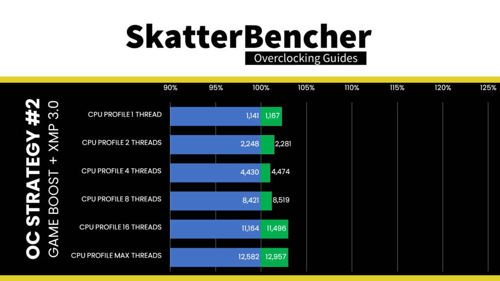
With Game Boost, we increase the processor frequency slightly over the stock settings. Therefore, while we expect some performance improvement, we don’t expect it to be enormous. We have the best performance improvement of +9.11% in Geekbench 5.
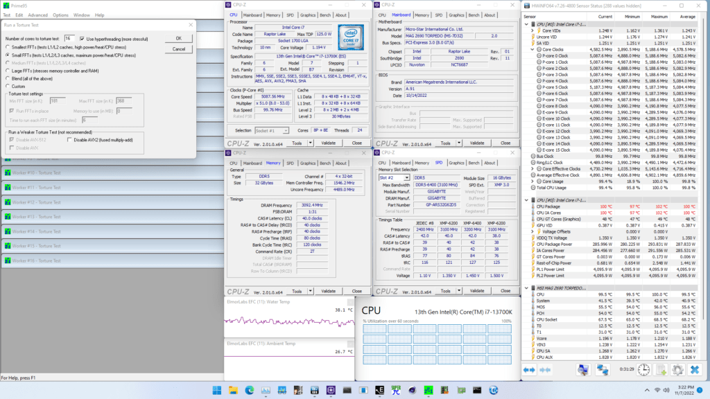
When running Prime 95 Small FFTs with AVX2 enabled, the average CPU P-core clock is 5083 MHz and average CPU E-core clock is 4202 MHz with 1.188 volts. The average CPU temperature is 100 degrees Celsius. The ambient and water temperature is 26.7 and 38.1 degrees Celsius. The average CPU package power is 287.8 watts.
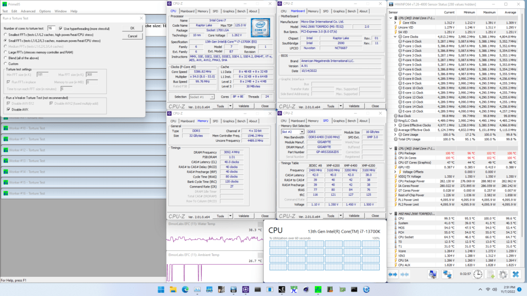
When running Prime 95 Small FFTs with AVX disabled, the average CPU P-core clock is 5353 MHz and average CPU E-core clock is 4256 MHz with 1.259 volts. The average CPU temperature is 100 degrees Celsius. The ambient and water temperature is 26.7 and 38.3 degrees Celsius. The average CPU package power is 283.0 watts.
OC Strategy #3: Turbo Ratio Offset + XMP 3.0
In our third overclocking strategy, we will use MSI’s Turbo Ratio Offset feature. The Turbo Ratio Offset is a unique approach to overclocking that lifts the default Turbo Ratio configuration by a specific number of bins. This enables you to configure a dynamic overclock while not digging too deep through the various BIOS options.
For our configuration, we choose a Turbo Ratio Offset of +5 for the P-cores and +2 for the E-cores. That will push the P-core frequency to up to 5.9 GHz and the E-core frequency to up to 4.4 GHz.
In addition to the Turbo Ratio Offset, we will also use Adaptive Voltage mode, which suits our dynamic overclock. To better understand the impact of our overclocked configuration, let’s have a closer look at these two Intel technologies.
Intel Turbo Ratios
Generally speaking, on Intel platforms, there are two ways to manually configure the CPU ratio: sync all cores or use turbo ratio configuration.
Sync All Cores sets a single fixed ratio applied to all cores. This is very much the historical way of Intel CPU overclocking. Turbo Ratio configuration allows us to modify the default Intel frequency specification and configure an overclock for various scenarios.
Before we go any further, there are three critical elements of understanding any Turbo Ratio configuration:
- You can configure the maximum allowed CPU core ratio for any amount of active cores
- You can configure the maximum allowed CPU core ratio for a given CPU core
- The turbo ratio configuration for P-core and E-cores is independent.
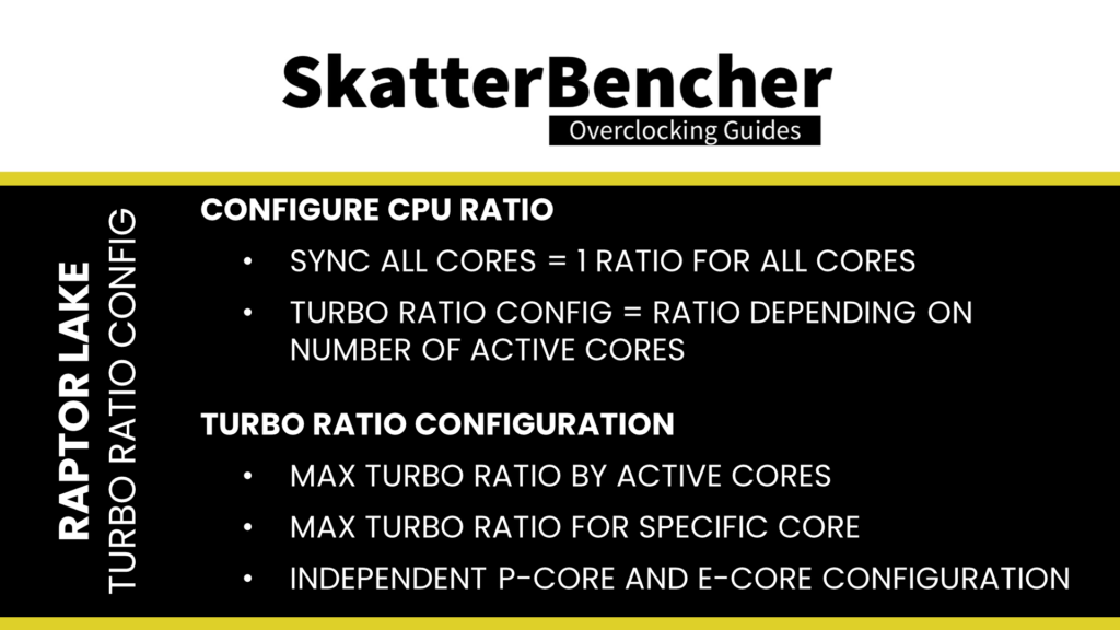
To explain the first point, let’s take the default configuration of the 13700K. The 13700K has a total of 8 P-cores. Therefore we can configure the maximum allowed P-core ratio for when 1 P-core is active, when 2 P-cores are active, all the way up to when 8 P-cores are active. The standard configuration allows up to 2 active P-cores to boost to 5.4 GHz and up to 8 active P-cores to boost to 5.3 GHz.
In our overclock, since we lift the Turbo Ratios by +5 bins, the configuration allows up to 2 active P-cores to boost to 5.9 GHz and up to 8 active P-cores to boost to 5.8 GHz.
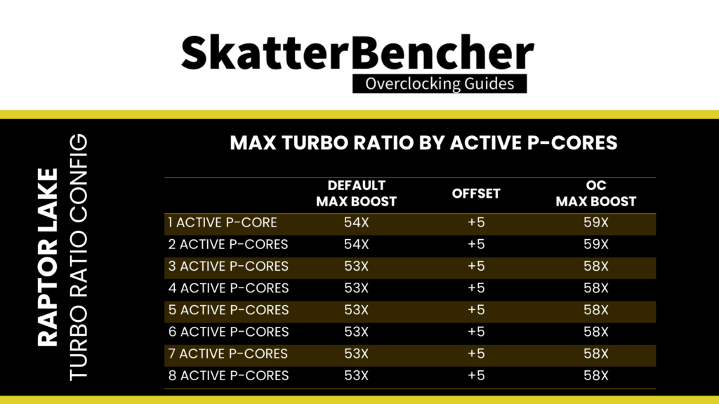
To explain the second point, again, let’s consider the 13700K default specification. While the 13700K has 8 identical P-cores, two of those cores are called the favored cores. The maximum allowed frequency for the favored cores is 5.4 GHz, whereas the other cores are limited to 5.3 GHz.
If we combine point 1 and point 2, we can identify the following scenarios:
- If 1 P-core is active and it is a favored P-core, then that core will run at 5.4 GHz
- If 1 P-core is active and it is not a favored P-core, then that core will run at 5.3 GHz
- If 2 P-cores are active and both are a favorite P-core, then both cores will run at 5.4 GHz
- If 2 P-cores are active and one is a favorite P-core while the other isn’t, then one core will run at 5.4 GHz, and the other will run at 5.3 GHz.
- If 2 P-cores are active and neither is a favorite P-core, then both cores will run at 5.3 GHz
- If 3 or more P-cores are active, then any P-core will run at 5.3 GHz.
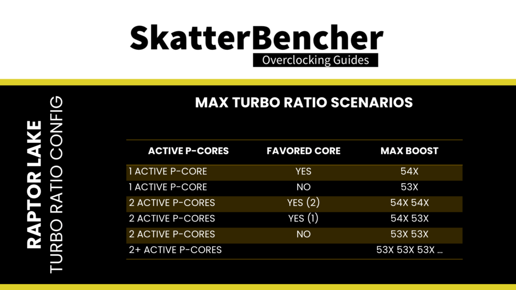
In our overclock, since we lift the Turbo Ratios by +5 bins, the configuration allows the favored P-cores to boost to 5.9 GHz and the other P-cores to boost to 5.8 GHz.
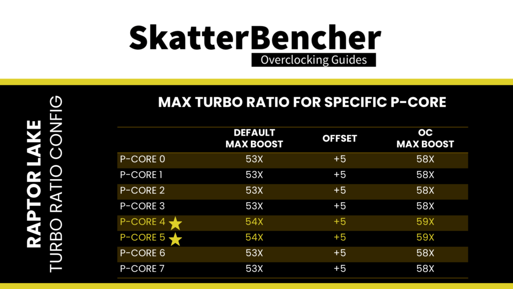
To explain the third point, again, let’s refer to the 13700K. The 13700K has a total of eight P-cores and 8 E-cores. While the P-cores can boost up to 5.4 GHz, the E-cores can only boost up to 4.2 GHz.
The P-core rules for maximum allowed frequency can also be applied to the E-cores. However, with one major caveat: the E-core CPU ratio can only be controlled in groups of 4 E-cores. So, for the 13700K, since it has eight E-cores in total, we can configure the maximum allowed core ratio for a total of two groups of four E-cores. However, we can still configure the maximum allowed frequency for 1 active E-core up to 8 active E-cores.
In our overclock, since we lift the Turbo Ratios by +5 bins for the P-cores and +2 bins for the E-cores, the configuration allows the favored P-cores to boost to 5.9 GHz, the other P-cores to boost to 5.8 GHz, and the E-cores to boost to 4.4 GHz.

Next, let’s have a look at the voltage configuration.
VccIA Voltage Rail
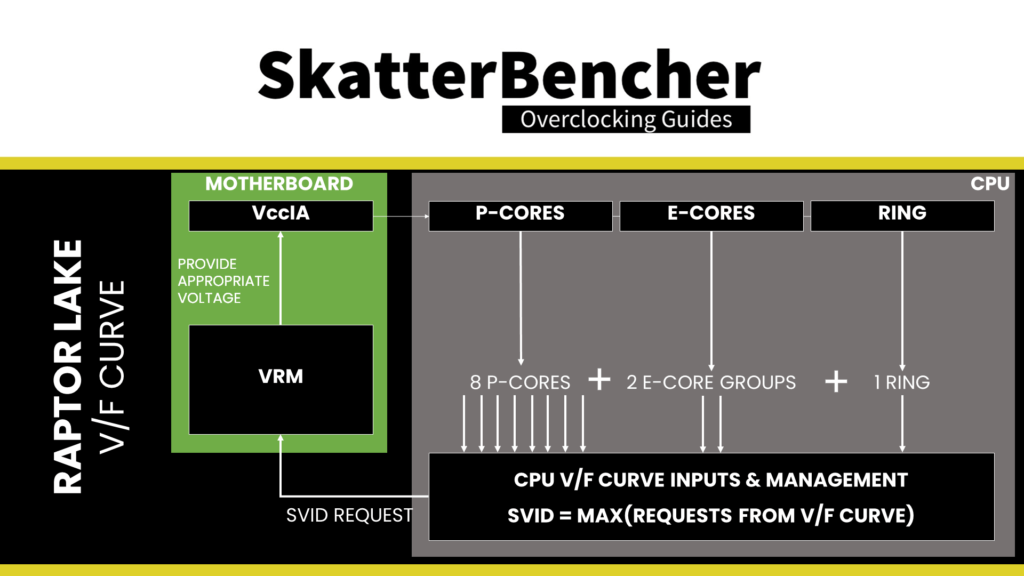
On Raptor Lake, the VccIA voltage rail drives the voltage for the CPU cores, P-core and E-core, and the Ring. That means a single voltage is used for all these parts of the CPU. How that voltage is configured is straightforward yet complex.

There are three key aspects to understanding how voltage is configured on Intel platforms: the CPU, the motherboard design, and the voltage regulator.

Let’s start with the CPU side of the story.
V/F Curves
An Intel CPU relies on many factory-fused voltage-frequency curves, or V/F curves, to regulate its dynamic compute performance behavior. A V/F curve describes the relationship between an operating frequency and the voltage required for that frequency. A lot of parts inside your CPU have a V/f curve, including those relevant to the VccIA voltage rail:
- Each of the 8 P-cores
- Each of the 2 E-core groups of 4 cores
- The ring
In the case of the Core i7-13700K, the VccIA voltage rail is affected by no less than 11 different voltage-frequency curves. Based on these V/F curves, to get a specific voltage provided via the VccIA voltage rail, the CPU issues an SVID request to the voltage controller. The VID requested is the highest among all the requested voltages according to every V/F curve affecting the voltage rail.
Let’s take an example:
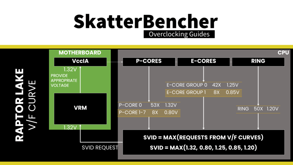
In this case, the highest voltage requested according to the relevant V/F curves is 1.32V by P-Core 0. This will be the VID request to the voltage controller.
Here’s another example:

In this case, the highest voltage requested according to the relevant V/F curves is 1.25V by E-Core Group 0. This will be the SVID request to the voltage controller.
The goal of the SVID voltage request from the CPU to the voltage regulator is that the effective voltage at the CPU die is equal to the requested voltage. However, as overclockers and enthusiasts know very well, that’s not always the case. That’s because there are a lot of electrical components between the voltage regulator and the CPU die.
To avoid the voltage delivered to the CPU die being lower than the requested voltage, we have two main tools: (1) AC-DC loadline and (2) VRM loadline.
AC DC Loadline
Plenty has been said and written about the AC-DC voltage loadline, so I won’t cover it in detail here. The long story short is that the AC-DC loadline is designed to account for the electrical impedance from the motherboard design, including the VRM components, the PCB layout, and quality.
The impedance can significantly affect the actual voltage at the CPU die. To avoid too big a difference between the requested and effective voltage, we can adjust for this in the motherboard BIOS. The adjustment consists of informing the CPU of the motherboard impedance via the AC loadline setting so the CPU can request a higher voltage to the voltage regulator.
For example, suppose it is known that a 1.4V voltage output by the voltage controller, as requested by the CPU, will result in an effective voltage of 1.35V at the CPU die.
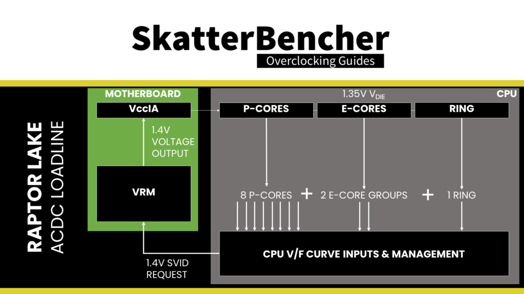
In that case, the AC loadline can be configured such that the CPU requests 1.45V instead.

VRM loadline
The VRM loadline setting determines how much the output voltage increases or decreases during a transient load. Transient means when the CPU goes from a low load to a high load or vice versa. Two parts of the VRM loadline are relevant for overclocking: Vdroop and Undershoot.
Vdroop is the decrease in voltage when the CPU goes from idle to load. You want your CPU to be stable in all scenarios, so knowing the lowest voltage the CPU will run at is very important. After all, if the voltage is too low, the overclock will be unstable.
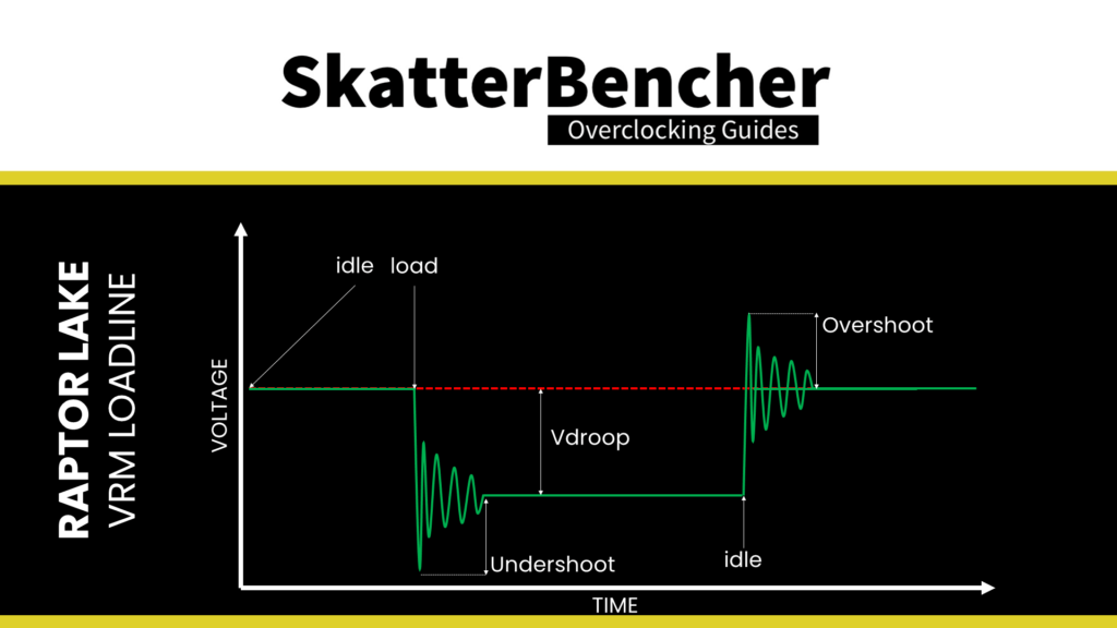
Undershoot and its counterpart, overshoot, is a brief voltage spike that occurs when the CPU switches from idle to load or from load to idle. These spikes cannot be measured easily and usually require an expensive oscilloscope to detect. I highly recommend the ElmorLabs article titled VRM Load-Line Visualized to see a great picture of undershoot and overshoot in action.
While undershoot and overshoot are temporary spikes, an undershoot that’s too low will also cause instability.
By adjusting the VRM loadline, we can mitigate both the Vdroop and Undershoot. In practice, it often helps us reduce the voltage under high load, resulting in a lower temperature and possibly higher turbo boost frequency.

Now that we know all this information let’s return to the core voltage.
Intel Adaptive Voltage Mode
There are two main ways of configuring the voltage for the CPU cores: override mode and adaptive mode.
- Override mode specifies a single static voltage across all ratios. It is mainly used for extreme overclocking purposes where stability at high frequencies is the only consideration.
- Adaptive mode is the standard mode of operation. In Adaptive Mode, the CPU relies on the V/F curves to set the appropriate voltage for the VccIA voltage rail.

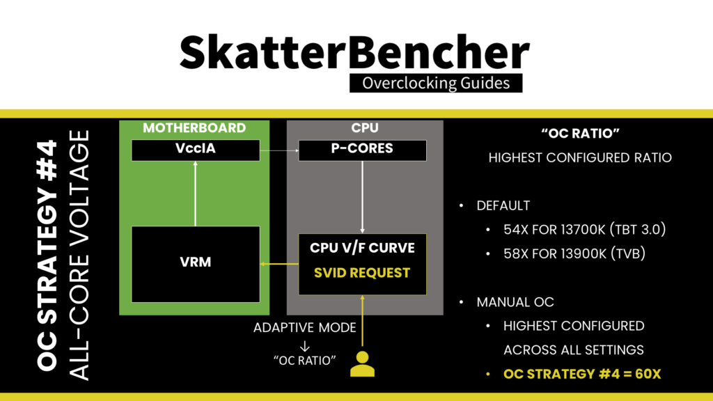
Both override and adaptive mode settings can be configured via the CPU registers. So, in effect, we control the CPU VID request to the voltage controller. This is Intel’s intended way of overclocking. Of course, most voltage controllers also allow independent configuration. For example, they enable us to configure a voltage offset to the requested voltage. It is often unclear from the motherboard BIOSes which method of setting the CPU core voltage we’re using when we type in the desired voltage.
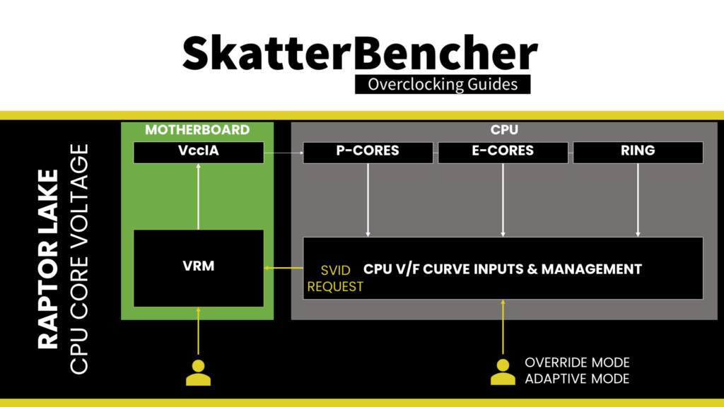
For the purpose of this guide, however, let’s ignore the capabilities of the voltage controllers and focus on Intel’s intended way of overclocking.
We can specify a voltage offset for override and adaptive modes. Of course, this doesn’t make much sense for override mode – if you set 1.35V with a +50mV offset, you could just set 1.40V – but it can be helpful in adaptive mode. The entire V/F curve can be offset by up to 500mV in both directions.
As I mentioned, Intel offers great granularity for tuning the many V/F curves inside the CPU. Let’s forget about the E-cores and Ring to keep things simple and assume a case where we set a global adaptive voltage for the CPU P-cores. Now let’s dig into what happens when we set a global adaptive voltage.
First, disregarding any user-set global or V/f point offsets, the adaptive voltage set in the BIOS is mapped against what’s called the “OC ratio.” The “OC Ratio” is the highest ratio configured for the CPU.
When you leave everything at default, the OC ratio is determined by the default maximum turbo ratio. In the case of the 13700K, that ratio is 54X, which is the Turbo Boost Max 3.0 frequency. In the case of the 13900K, that ratio would be 58X, which is the Thermal Velocity Boost Frequency. When you manually overclock, the OC ratio is the highest ratio you configure across all the various settings and options.
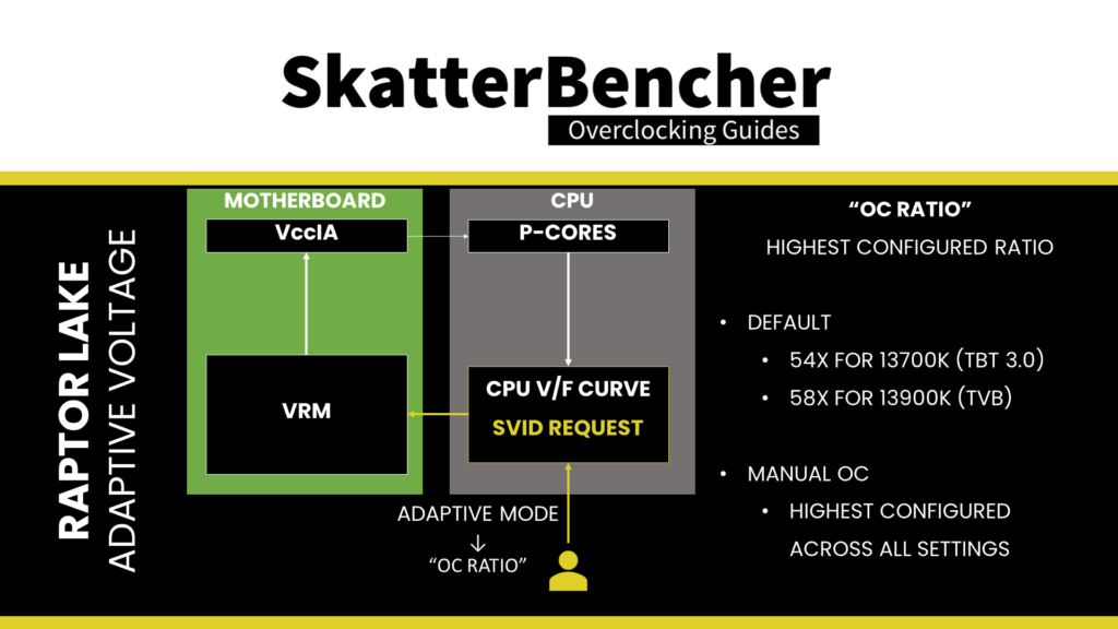
Second, specific rules govern what adaptive voltage can be set.
A) the voltage set for a given ratio n must be higher than or equal to the voltage set for ratio n-1.
Suppose our 13700K runs 54X at 1.30V. In that case, setting the adaptive voltage, mapped to 54X, lower than 1.30V, is pointless. 54X will always run at 1.30 or higher. Usually, BIOSes will allow you to configure lower values. However, the CPU’s internal mechanisms will override your configuration if it doesn’t follow the rules.
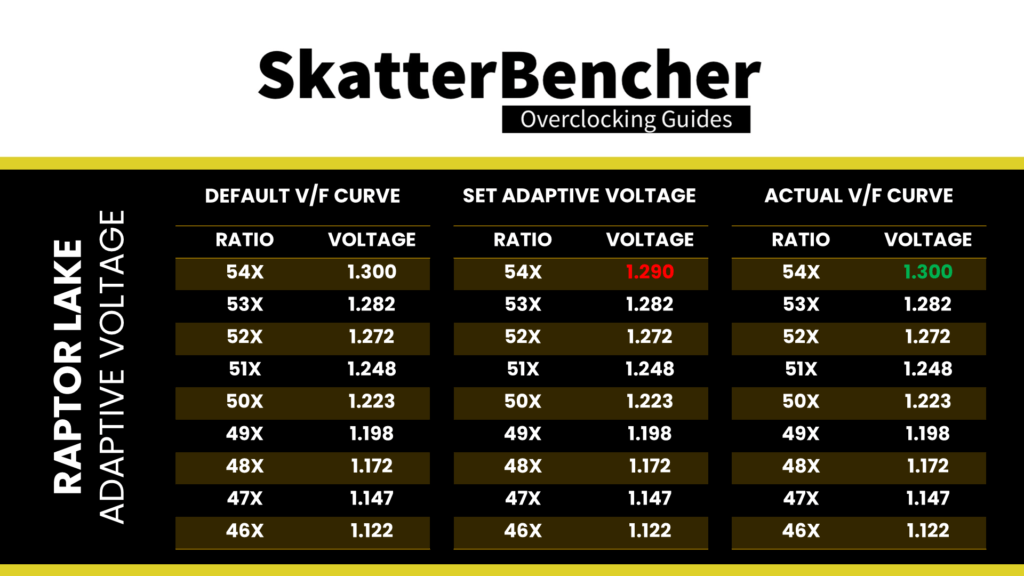
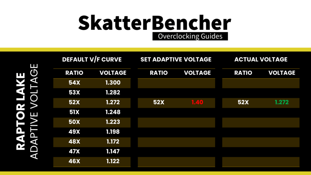
B) the adaptive voltage configured for any ratio below the maximum default turbo ratio will be ignored.
Take the same example of the 13700K, which is specified to run 54x at 1.30V. If you try to configure all cores to 52x and set 1.40V, the CPU will ignore this because it has its own factory-fused target voltage for all ratios up to 54X and will use this voltage. You can only change the voltage of the OC Ratio, which, as mentioned before, on the 13700K, is 54X and up.
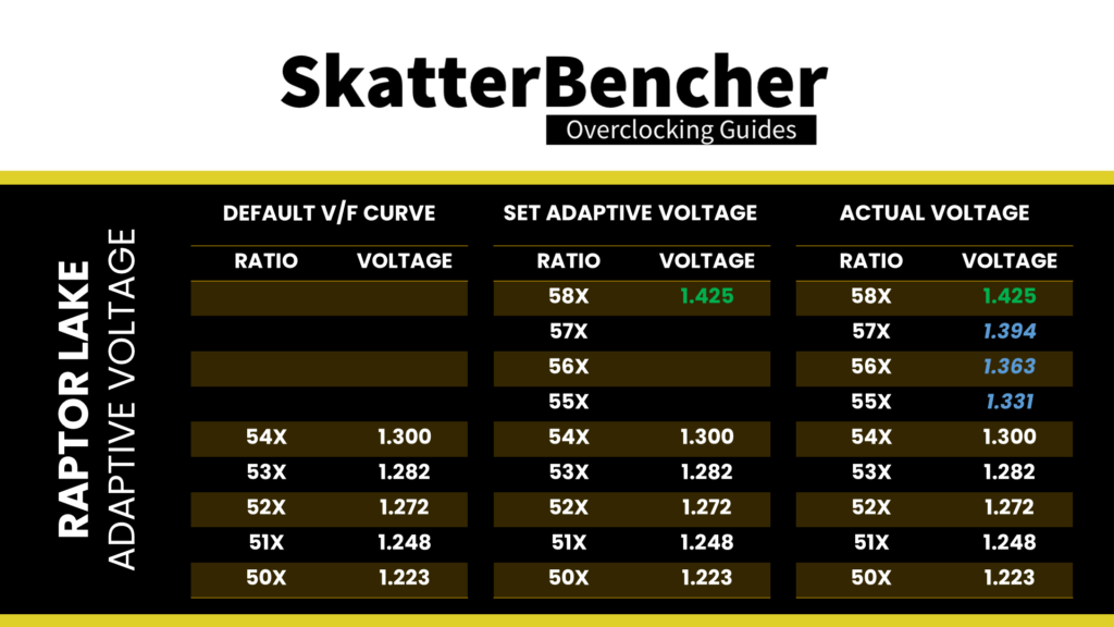
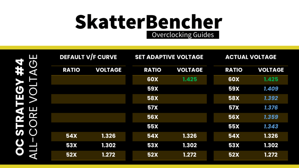
C) for ratios between the OC Ratio and the next highest factory-fused V/f point, the voltage is interpolated between the set adaptive voltage and the factory-fused voltage.
Returning to our example of our 13700K specified to run 54X at 1.30V, let’s say we manually configure the OC ratio to be 58X at 1.425V. The target voltage for ratios 55X, 56X, and 57X will now be interpolated between 1.30V and 1.425V.
So, in conclusion.
The adaptive voltage set in BIOS is mapped against the “OC Ratio.” Unless explicitly programmed, the OC Ratio is the highest ratio configured for the CPU across all settings, including by core usage, per core ratio limit, and OCTVB. The voltage for ratios lower than the OC ratio is set either by its factory-fused V/f point or, if there’s no V/f point, interpolated between the next and previous V/f point.
13700K V/F Curve Discussion
In SkatterBencher #31, I covered the Alder Lake V/F curve in detail. Since Raptor Lake is very similar to Alder Lake, we can follow the same procedure to extract the voltage-frequency curve for this Core i7-13700K processor.
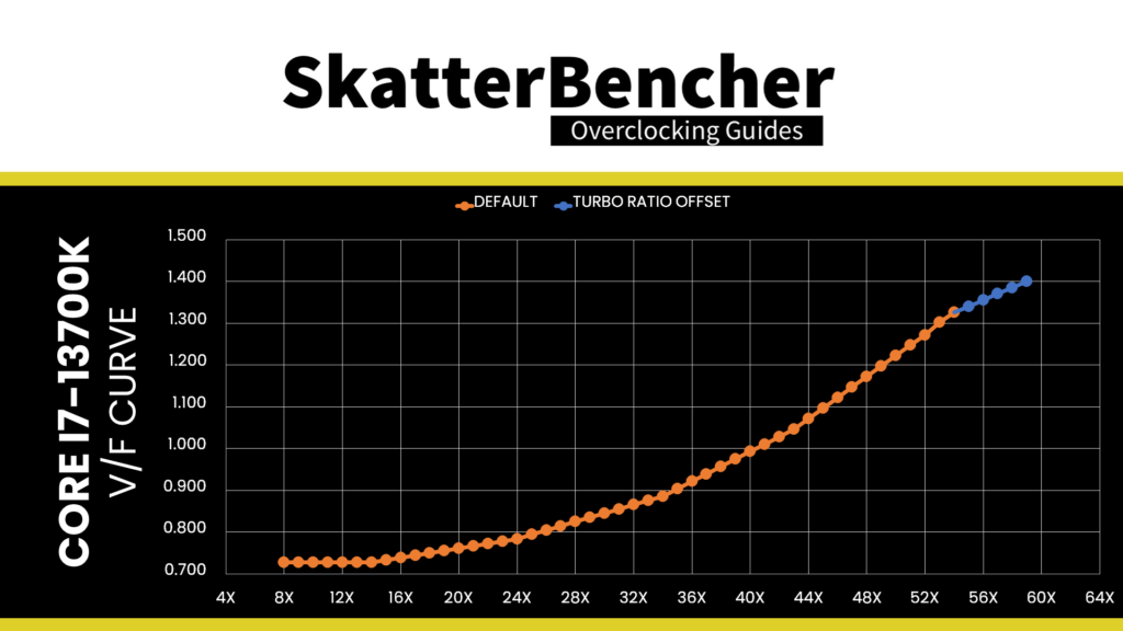
In our overclocking example, we set the adaptive voltage to 1.4V. As explained, the adaptive voltage is mapped against the “OC Ratio,” and in this OC strategy, that’s 59X. As a result, the new voltage-frequency curve looks as follows.
Thermal Velocity Boost & BCLK 100 MHz
I modify two additional settings for this overclock: disabling Thermal Velocity Boost Voltage Optimizations and forcing the BCLK to run at exactly 100 MHz.
Thermal velocity boost is an Intel technology that exploits the fact that CPUs need less voltage to run a specific frequency when the operating temperature is lower. When this setting is enabled, the CPU automatically adjusts the voltage according to the operating temperature. As we want manual control over the operating voltage to ensure stability, it’s prudent to disable this function.
Forcing the BCLK to run at exactly 100 MHz has little to do with stability or performance and everything to do with personal preference.
BIOS Settings & Benchmark Results
Upon entering the BIOS
- In Advanced Mode, click XMP Profile 1
- Enter the Overclocking settings menu
- Set P-Core Ratio Apply Mode to Turbo Ratio Offset
- Set P-Core Turbo Ratio Offset Value to +5
- Set E-Core Ratio Apply Mode to Turbo Ratio Offset
- Set E-Core Turbo Ratio Offset Value to +2
- Enter the Advanced CPU Configuration submenu
- Set BCLK 100MHz Lock On to Enabled
- Set TVB Voltage Optimizations to Disabled
- Leave the Advanced CPU Configuration submenu
- Ensure CPU Cooler Tuning is set to Water Cooler (PL1: 4096W)
- Set CPU Core Voltage Mode to Adaptive Mode
- Set CPU Core Voltage to 1.400
Then save and exit the BIOS.
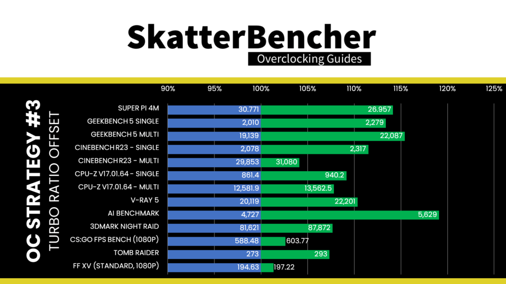
We re-ran the benchmarks and checked the performance increase compared to the default operation.
- SuperPI 4M: +14.15%
- Geekbench 5 (single): +13.38%
- Geekbench 5 (multi): +15.40%
- Cinebench R23 Single: +11.50%
- Cinebench R23 Multi: +4.11%
- CPU-Z V17.01.64 Single: +9.15%
- CPU-Z V17.01.64 Multi: +7.79%
- V-Ray 5: +10.35%
- AI Benchmark: +19.08%
- 3DMark Night Raid: +7.66%
- CS:GO FPS Bench: +2.60%
- Tomb Raider: +7.33%
- Final Fantasy XV: +1.33%
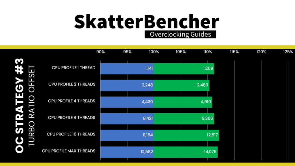
Here are the 3DMark CPU Profile scores at stock
- CPU Profile 1 Thread: +11.22%
- CPU Profile 2 Threads: +10.32%
- CPU Profile 4 Threads: +10.84%
- CPU Profile 8 Threads: +11.22%
- CPU Profile 16 Threads: +12.12%
- CPU Profile Max Threads: +11.87%
Of course, we expected a significant performance improvement after increasing the CPU P-core frequency by 500 MHz and the E-core frequency by 200 MHz. And that’s also what we see with double-digit performance improvements in both single-threaded and multi-threaded benchmark applications. We see the highest performance improvement of +19.08% in AI Benchmark
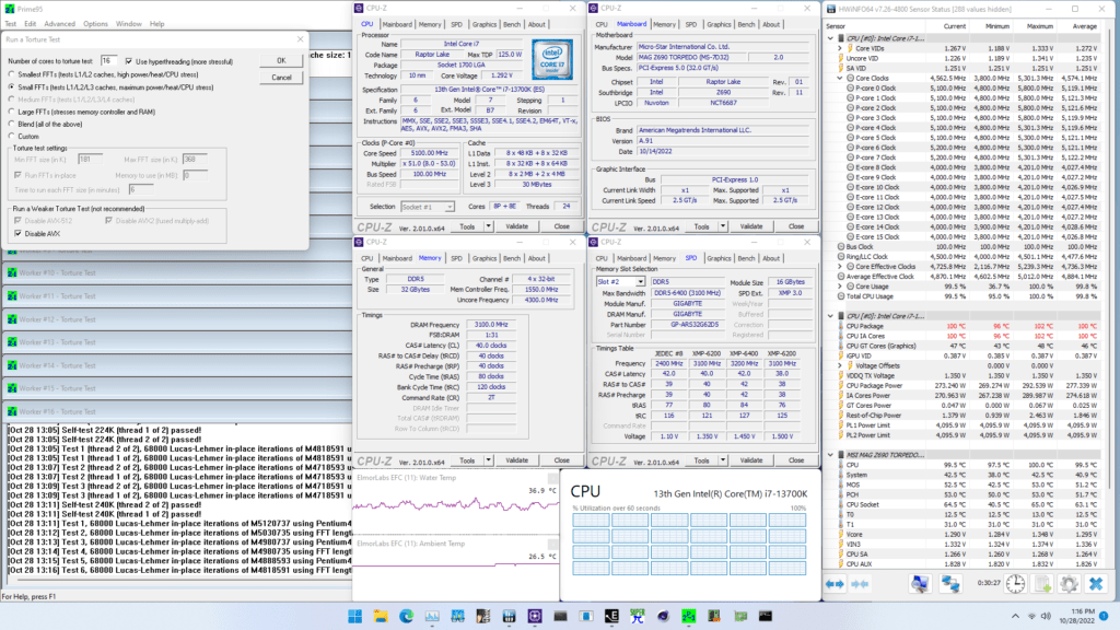
When running Prime 95 Small FFTs with AVX2 enabled, the average CPU P-core clock is 4848 MHz and average CPU E-core clock is 3849 MHz with 1.207 volts. The average CPU temperature is 100 degrees Celsius. The ambient and water temperature is 26.4 and 36.4 degrees Celsius. The average CPU package power is 280.4 watts.
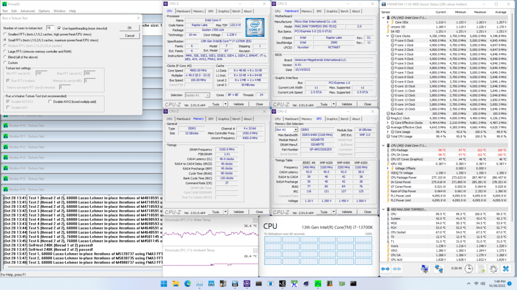
When running Prime 95 Small FFTs with AVX disabled, the average CPU P-core clock is 5120 MHz and average CPU E-core clock is 4027 MHz with 1.272 volts. The average CPU temperature is 100 degrees Celsius. The ambient and water temperature is 26.5 and 36.9 degrees Celsius. The average CPU package power is 277.3 watts.
OC Strategy #4: Manual + XMP 3.0
In our fourth and final overclocking strategy, we resort to advanced manual overclocking to squeeze more performance out of our system. We have a couple of objectives:
- We will try to get at least some of our P-cores to reach 6 GHz
- We will try to push at least one E-core group to a higher frequency
- We will optimize the all-core Prime95 settings to achieve better all-core frequency.

I will try to explain how I approached each objective’s tuning and BIOS configuration.
Raptor Lake 13700K P-Core Tuning
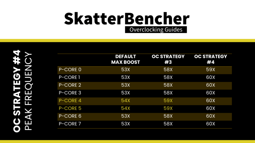
To push the P-cores higher, we can rely on the same technology as our previous OC strategy: Turbo Ratios. However, we will manually configure the Turbo Ratio rather than depending on an offset. This allows us to have more than 2 active P-cores boost to the highest frequency. Our manual configuration is as follows:
- Up to 4 active P-cores to 6 GHz,
- Up to 5 active P-cores to 5.9 GHz,
- Up to 6 active P-cores to 5.8 GHz, and
- Up to 8 active P-cores to 5.7 GHz.
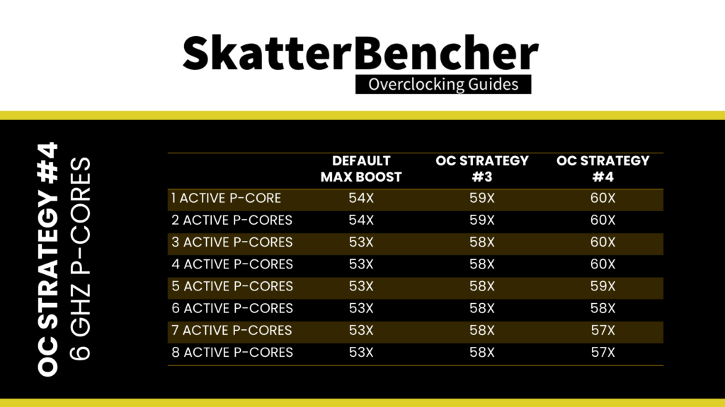
As you can see, we target the P-cores to boost 100 MHz higher than our previous OC strategy. I hear you ask already … if you can push it to 6 GHz, why not also do it in your last strategy?
That’s easy: because not all P-cores can boost to 6 GHz.
As it turns out, P-core 0 is not as good as the others. So, to prevent that core from boosting to 6 GHz, we use the Per P-core Ratio Limit function. Here we define the maximum allowed ratio for a given P-core regardless of the Turbo Ratio configuration.
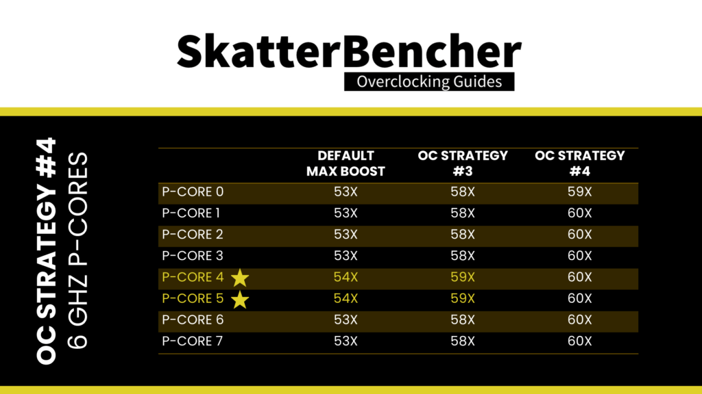
For example, let’s say we have four active P-cores, and one of the active cores is Core 0. In this case, according to the Turbo Boost configuration, all P-cores can boost to 6 GHz. However, since the Core 0 Ratio Limit is 59X, only three of the four cores will run at 6 GHz, and the other core, Core 0, will run at 5.9 GHz.
The last topic we must discuss is the voltage for our 6 GHz P-cores. We will rely on the Advanced Voltage Offset function for this strategy, better known as V/F Points. Since there’s quite a bit to say about V/F Points on Raptor Lake, we will cover it when discussing all-core Prime95 finetuning.
For now, it’s sufficient to say that we use a voltage of 1.425V to reach 6 GHz. I validated this overclock using CoreCycler for elementary tuning and manual stability validation of the frequency/voltage.
Raptor Lake 13700K E-Core Tuning
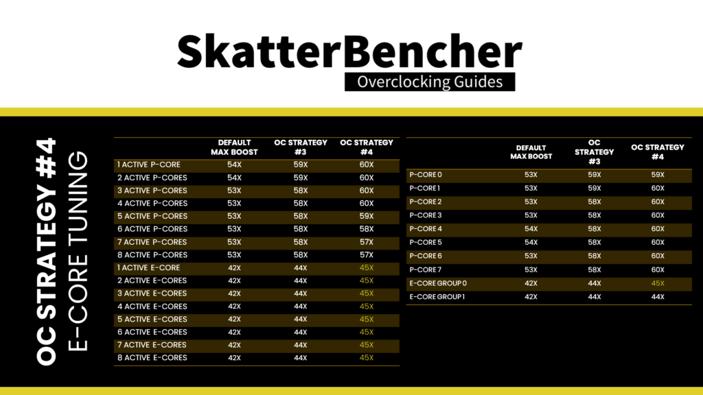
Similar to the P-cores, we use a ratio limiter to have only the best E-core group boost to the highest frequency. To make things very short: I add one additional step to the Turbo Ratio Offset, allowing the E-cores to run up to 4.5 GHz, and restrict E-core Group 1 to 44X.
Raptor Lake 13700K All Core Tuning
Last but not least, we dig into finetuning the all-core frequency for heavy workloads like Prime95. Getting our system to adapt to heavy workloads is a core aspect of our modern, dynamic overclocking approach. It requires several pieces to come together in harmony.
The pieces include:
- Ensuring continued stability of the high frequency and high voltage for single-threaded or light workloads
- Ensuring the frequency decreases appropriately with the increased workload
- Ensuring the voltage is sufficient to support the high frequency at higher workloads
- Ensuring the system is also stable during transient conditions.

Piece 1: Stability of Peak Frequency
For the first piece of the puzzle, we already have the answer. As I mentioned before, all cores of this CPU can run at 6 GHz with 1.425V except for Core 0. Using the Per Core Ratio Limit function, we can configure the system so that all cores will boost to 6 GHz but limit Core 0 to a maximum of 5.9 GHz.
Piece 2: Stability of All-Core Frequency
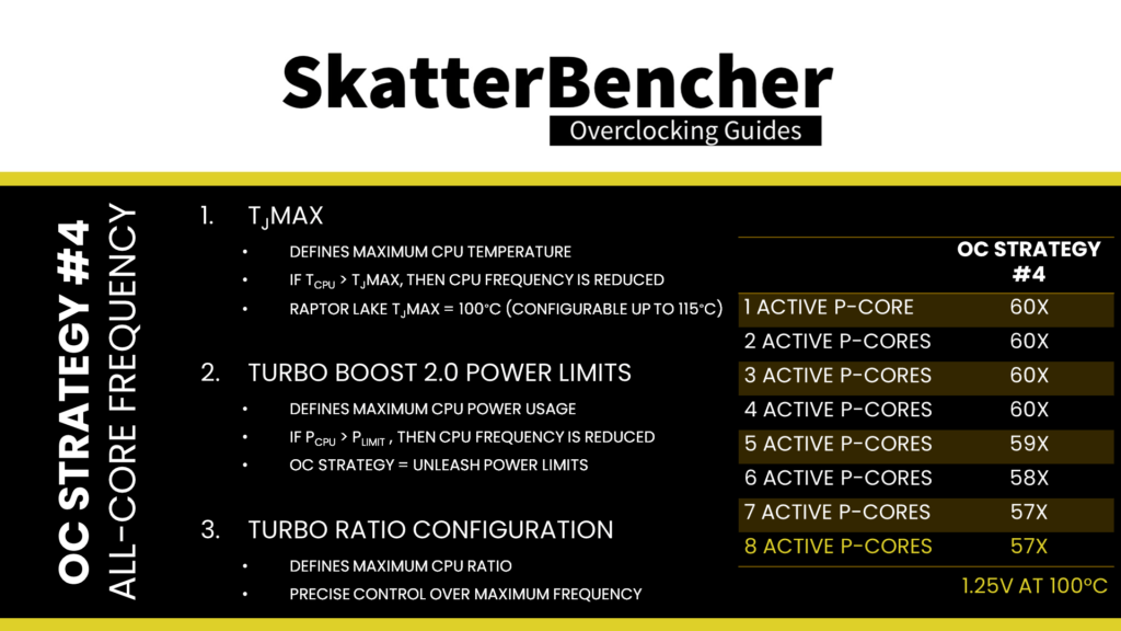
We have several tools at our disposal for the second piece of the puzzle – reducing the operating frequency as the workload increases. The tools include TjMax, Turbo Boost 2.0 power limits, and Turbo Boost ratios.
Tjunction max, or TjMax, is the maximum thermal junction temperature that a processor is allowed to run at. If the temperature exceeds TjMax, internal thermal control mechanisms will reduce the operating frequency until the temperature is below TjMax.
The TjMax for Raptor Lake CPUs is 100 degrees Celsius; however, it can be manually increased to 115 degrees. When the CPU goes above 100 degrees, it will automatically reduce the operating frequency. As temperature increases with heavier, multi-core workloads, it can be used to appropriately reduce the operating frequency. However, we prefer to allow up to the Intel default temperature limit of 100 degrees Celsius to maximize performance.
As discussed before, Turbo Boost 2.0 power limits manage the total power used for the CPU. In practical terms, it reduces the CPU operating frequency to prevent the CPU from exceeding a specific power use. As power usage increases with heavier, multi-core workloads, it can be used to appropriately reduce the operating frequency. However, since we unleash the power limits to effectively no constraint, it won’t be helpful for this OC strategy.
As discussed, the Turbo Boost ratio configuration allows us to specify a maximum CPU ratio for a given number of active cores. Therefore, we can precisely set the maximum frequency when all cores are loaded.
In this case, I find that the maximum stable frequency for an all-core workload is 5.7 GHz. In an all-core heavy workload like Prime95 with AVX disabled, the maximum voltage at the maximum temperature of 100 degrees Celsius is about 1.25V. This is an essential input for when we get to tune the voltage-frequency curve.
Piece 3: Voltage for All-Core Frequency
Knowing which voltage you need to run at for your best all-core workload is great, but the difficulty comes when you have to set the voltage. After all, using a dynamic voltage to match our dynamic overclock means we don’t have complete control over the voltage for each specific frequency. There are two ways to approach dynamic voltage configuration on Intel platforms: adaptive voltage or advanced voltage offset. You can use these methods separately or together.
As I explained before, when we set an adaptive voltage, we map it against the OC Ratio, which is the highest of all ratios set. In this case, the OC Ratio will be 60X. The voltage for 59X is then interpolated between the voltage mapped against the OC Ratio and the next factory-fused V/F point, which for the 13700K is 54X.
Advanced voltage offset, or V/F Points, is an extension of the Adaptive Voltage as it exposes some of the points on the V/f curve to the end-user and allows for manual adjustment of these points. The amount of V/f points is not architectural and can differ between SKUs.
The primary purpose of the Advanced Voltage Offset is to provide end-users with the ability to under-volt their CPUs at specific parts of the V/f curve. In addition to undervolting, this feature also allows overvolting.
The Advanced Voltage Offset function is commonly used in two ways.
- First, you configure a positive voltage offset for the highest V/f point. This helps achieve a higher single-threaded boost frequency.
- Second, you configure a negative voltage offset for the second-highest V/f point. This helps achieve lower voltage for all-core boost, which results in a lower temperature in all-core boost, and thus potential additional overclocking headroom.
On Raptor Lake, there are 15 distinct voltage-frequency points. However, only points one to eleven are used. Furthermore, some points can be copies of other points. On the 13700K, the V/F points are as follows:
- V/F Point 1: 8X
- V/F Point 2: 14X
- V/F Point 3: 24X
- V/F Point 4: 34X
- V/F Point 5: 43X
- V/F Point 6: 51X
- V/F Point 7: 52X
- V/F Point 8: 53X
- V/F Point 9: 54X
- V/F Point 10: 54X
- V/F Point 11: 54X
V/F Point 8 matches the Turbo Boost 2.0 frequency, V/F Point 9 matches the Turbo Boost 3.0 frequency, and V/F Point 11 matches the OC ratio. V/F Point 10 is a copy of V/F Point 9.

Ideally, we would now adjust the V/F Curve with the following modifications:
- V/F Points 6, 7, 8, and 9: offset with a negative value to undervolt the CPU. This will reduce the effective voltage when the CPU reduces the frequency in extreme workloads, resulting in higher average frequencies
- V/F Point 11: offset with a positive value to overvolt the CPU. This will enable additional frequency headroom, allowing us to push the CPU frequency higher in single-threaded or light workloads.
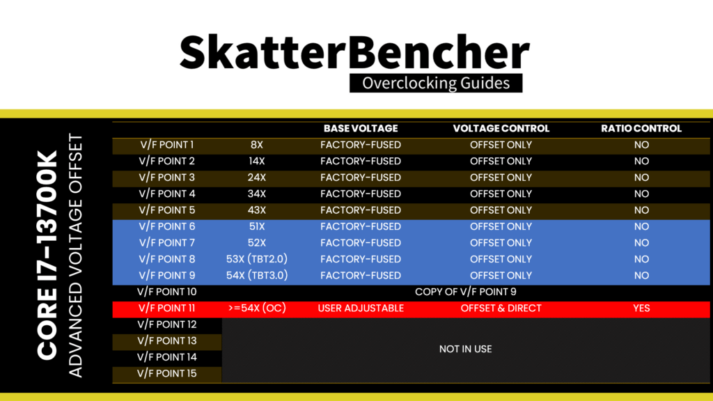
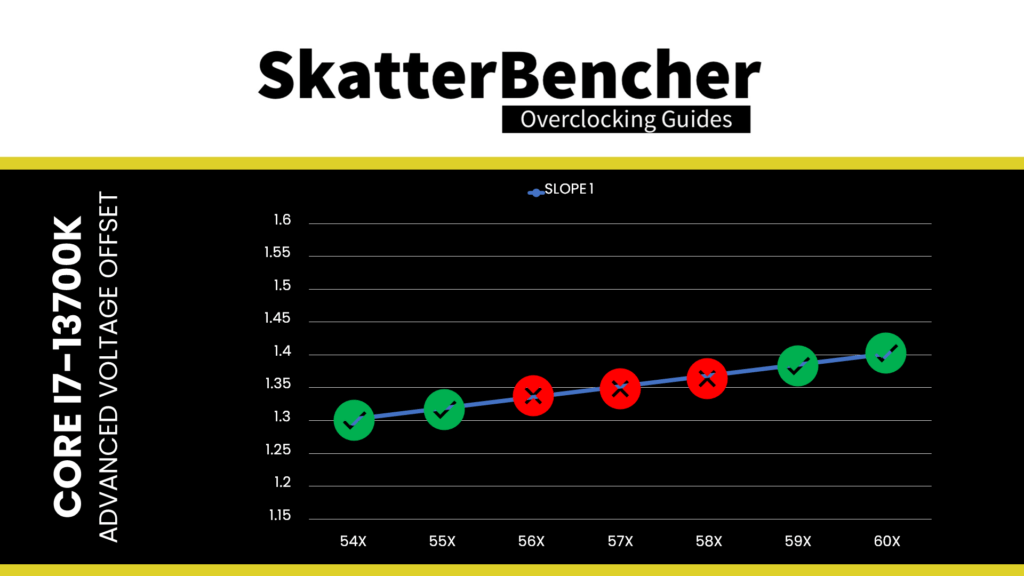
Note that V/F Points 9 and 11, mapped to ratios 54X and 60X in this OC Strategy, effectively control the voltage for ratios 55X, 56X, 57X, 58X, and 59X. The tricky part is that the V/F curve slope, as determined by those two V/F points, must accommodate light and heavy as well as single and multi-threaded workloads.

If your single-core frequency doesn’t need high voltage, the too-gentle slope may not accommodate high-frequency, light, multi-core workloads. If you need sufficient voltage for all-core workloads at high frequency, then the too-steep slope may set a too-high voltage for the single-core frequency.
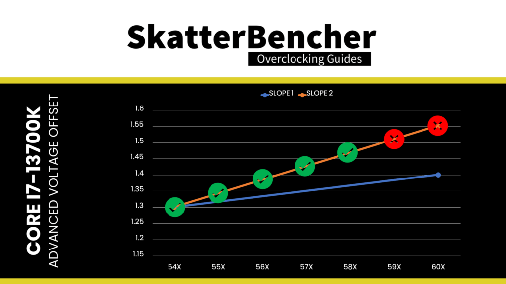
Lastly, unfortunately, it looks like the implementation of the V/F Points is not mature yet. There are quite a few issues when using it for a daily overclock. Two problems, in particular, can be frustrating:
- Sometimes the V/F Points don’t work correctly in combination with 100 MHz BCLK. An easy workaround is to have the BCLK frequency slightly lower or higher than 100 MHz.
- Sometimes not all points are exposed in the BIOS. In the example of the Z690 Torpedo EK X and the A91 beta BIOS, I’m using, only V/F Point 11 is available. Programming V/F Point 11 also programs V/F Point 9 and 10 to the same value.

To return to my example, I use the following advanced voltage offsets:
- V/F Point 6: 51X, -15mV
- V/F Point 7: 52X, -35mV
- V/F Point 8: 53X, -65mV
- V/F Point 9: 54X, +100mV
- V/F Point 10: 54X, +100mV
- V/F Point 11: 54X, +100mV
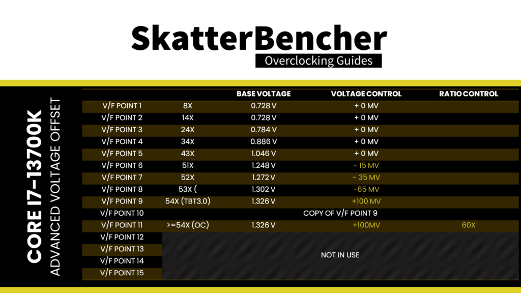
That gives the following very awkward voltage frequency curve.
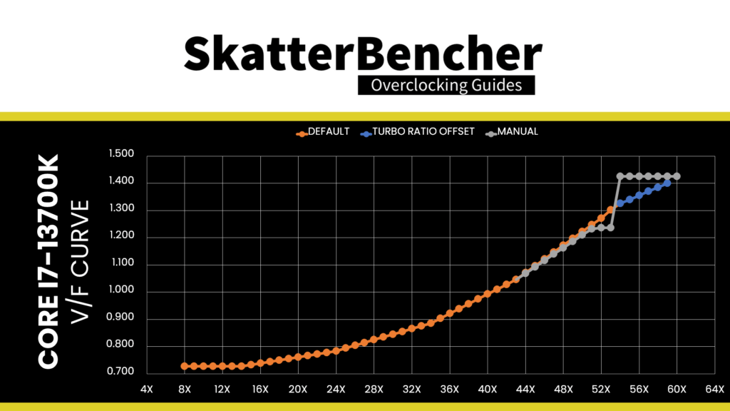
To clarify,
- the +100mV offset for V/F Points 9, 10, and 11 are because I can’t program them independently on this BIOS version.
- The -65mV offset for V/F Point 8 maximizes the undervolt at 5.3 GHz to push the CPU as much as possible to 5.4 GHz in heavy all-core workloads like Prime95.
- The -35mV and -15mV offset for V/F Points 7 and 6 ensure the curve remains monotonic. If I didn’t configure these points, the voltage for 53X would not go lower than that for 52X, which is factory-fused to 1.27V.
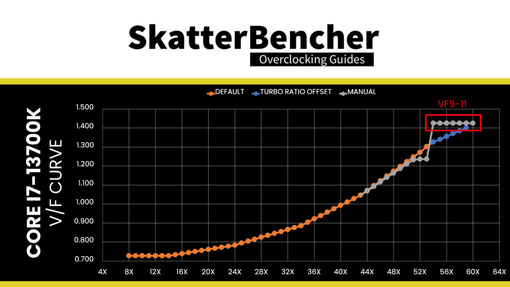
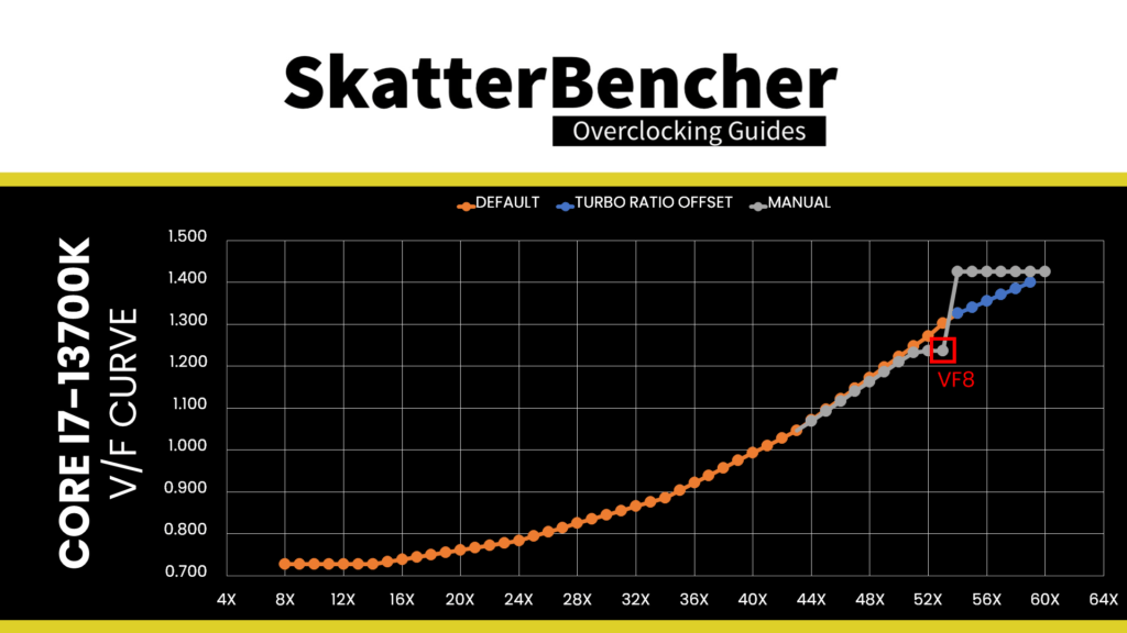
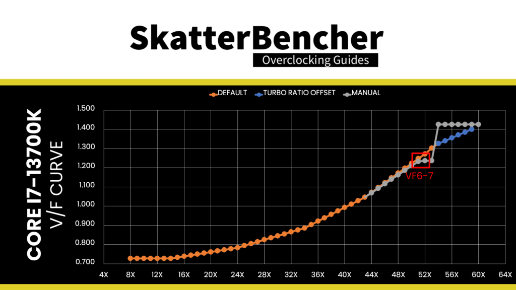
Piece 4: Transient Conditions
The last piece of the puzzle is undoubtedly the most challenging yet intangible: transient conditions.
A transient condition is when the CPU goes from idle to load, load to idle, few cores to many cores, or any similar situation. A vital characteristic of the transient condition is that the voltage and current change instantly and rapidly. This puts stress on all the electrical components, including and most prominently, the VRM.
As discussed, transient loads may cause undershoot and overshoot of the voltage to the CPU, which can invoke instability. However, it is not an exact science, and instability can appear unexpectedly. Therefore, it is tough to mitigate this apart from ensuring sufficient voltage margin to adapt to any transient condition.
The primary way to mitigate transient issues includes adjusting the VRM loadline. Still, you can use the ACDC loadline or change the Turbo Ratios to prevent big spikes. For example, while 5.7GHz may be stable in an all-core load, it may not be stable when coming from idle or a one-core load. Suppose neither VRM loadline nor ACDC loadline tuning helps. In that case, limiting the all-core frequency to 5.6 GHz may be required to avoid instability during transient conditions.

If all this sounds pretty difficult to tune for … it’s because it is. When you’re close to your best overclock, you fight everything: turbo ratios, voltages, temperatures, etc. The only way to win is to keep finetuning, adjusting, and deciding where to compromise.
As you’ll see in my overclocking settings, I rely on an ACDC loadline setting of Mode 2, which differs from the default of Mode 1, and an LLC loadline of also Mode 2. While I can’t say this is the best configuration outright for this platform, it is the best setting for my specific system and overclock configuration.
BIOS Settings & Benchmark Results
Upon entering the BIOS
- In Advanced Mode, click XMP Profile 1
- Enter the Overclocking settings menu
- Set P-Core Ratio Apply Mode to Turbo Ratio
- Set Number of P-Core of Group 1 to 4
- Set Target P-Core Turbo Ratio Group 1 to 60
- Set Number of P-Core of Group 2 to 5
- Set Target P-Core Turbo Ratio Group 2 to 59
- Set Number of P-Core of Group 3 to 6
- Set Target P-Core Turbo Ratio Group 3 to 58
- Set Number of P-Core of Group 4 to 8
- Set Target P-Core Turbo Ratio Group 4 to 57
- Set Per P-Core Ratio Limit to Manual
- Set P-Core 0 to 59
- Set P-Core 1 to 7 to 60
- Set E-Core Ratio Apply Mode to Turbo Ratio Offset
- Set E-Core Turbo Ratio Offset Value to +3
- Set Per E-Core Ratio Limit to Manual
- Set E-Core 0-3 to 45
- Set E-Core 4-7 to 44
- Enter the Advanced CPU Configuration submenu
- Set BCLK 100MHz Lock On to Enabled
- Set CPU Lite Load to Mode 2
- Set TVB Voltage Optimizations to Disabled
- Leave the Advanced CPU Configuration submenu
- Set CPU Ratio Offset When Running AVX to -2
- Ensure CPU Cooler Tuning is set to Water Cooler (PL1: 4096W)
- Enter the DigitALL Power submenu
- Set CPU Loadline Calibration Control to Mode 2
- Leave the DigitALL power submenu
- Set CPU Core Voltage Mode to Advanced Offset Mode (VF Point)
- Enter the Advanced Offset Mode (VF Point) submenu
- For Voltage Offset When Running CPU Ratio x51,
- Set Voltage Offset Control to –
- Set Voltage Offset Target to 0.015
- For Voltage Offset When Running CPU Ratio x52,
- Set Voltage Offset Control to –
- Set Voltage Offset Target to 0.035
- For Voltage Offset When Running CPU Ratio x53,
- Set Voltage Offset Control to –
- Set Voltage Offset Target to 0.065
- For Voltage Offset When Running CPU Ratio x60,
- Set Voltage Offset Control to +
- Set Voltage Offset Target to 0.100
- For Voltage Offset When Running CPU Ratio x51,
- Leave the Advanced Offset Mode submenu
Then save and exit the BIOS.
We re-ran the benchmarks and checked the performance increase compared to the default operation.
- SuperPI 4M: +20.31%
- Geekbench 5 (single): +16.72%
- Geekbench 5 (multi): +16.08%
- Cinebench R23 Single: +13.81%
- Cinebench R23 Multi: +5.88%
- CPU-Z V17.01.64 Single: +12.12%
- CPU-Z V17.01.64 Multi: +8.18%
- V-Ray 5: +12.20%
- AI Benchmark: +21.94%
- 3DMark Night Raid: +7.89%
- CS:GO FPS Bench: +2.98%
- Tomb Raider: +9.52%
- Final Fantasy XV: +2.94%
Here are the 3DMark CPU Profile scores at stock
- CPU Profile 1 Thread: +12.62%
- CPU Profile 2 Threads: +13.03%
- CPU Profile 4 Threads: +10.86%
- CPU Profile 8 Threads: +9.29%
- CPU Profile 16 Threads: +10.47%
- CPU Profile Max Threads: +4.09%
While we hit 6 GHz on most of the cores and saw some slight performance improvements over our Turbo Ratio Offset OC Strategy, overall, it’s a minor improvement. Nevertheless, we can be happy to achieve the best performance in all of our benchmarks. The highest performance improvement is in AI Benchmark with +21.94%.
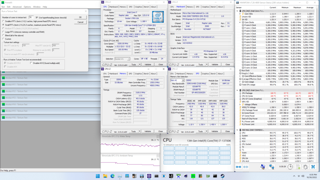
When running Prime 95 Small FFTs with AVX2 enabled, the average CPU P-core clock is 5090 MHz and average CPU E-core clock is 4080 MHz with 1.182 volts. The average CPU temperature is 100 degrees Celsius. The ambient and water temperature is 26.2 and 38.3 degrees Celsius. The average CPU package power is 255.6 watts.
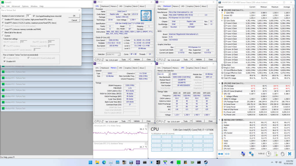
When running Prime 95 Small FFTs with AVX disabled, the average CPU P-core clock is 5273 MHz and average CPU E-core clock is 4241 MHz with 1.256 volts. The average CPU temperature is 99 degrees Celsius. The ambient and water temperature is 26.7 and 38.5 degrees Celsius. The average CPU package power is 256.8 watts.
Intel Core i7-13700K: Conclusion
Alright, let us wrap this up.
The Core i7-13700K overclocking experience was a mixed bag.
On the upside, the 13700K shows huge overclocking potential. Hitting 6 GHz on all but one core and 5.7 GHz in all-core workloads is extremely impressive. Furthermore, I’m glad to see this overclocking potential can be extracted on even a low-end Z690 motherboard like the Torpedo EK X.
It was pretty neat to see that the LiteBlock concept worked well with Raptor Lake. The maximum VRM temperature during a Prime95 workload was less than 60 degrees Celsius.
On the downside, tuning the voltage remains quite a challenge. While the V/F points have improved from Alder Lake, the overclocking headroom of Raptor Lake warrants more flexibility. Since there are unused V/F points available, why not open these up to user configuration? That would help enthusiasts build their own V/F curve on top of the factory-fused curve.
However, I want to be clear: the minor downsides fade away compared to the significant upsides. Raptor Lake is a fantastic overclocking platform. I’m sure enthusiasts will find joy in pushing their 13700K to their limit.
Anyway, that’s all for today! I want to thank my Patreon supporters for supporting my work. As per usual, if you have any questions or comments, feel free to drop them in the comment section below.
See you next time!
2 Phases 1 Raptor Lake - SkatterBencher
[…] this video is long overdue. I’ve wanted to tackle this subject since I published the 13700K SkatterBencher guide in November last […]
Ferenc
Hello.
I was wondering… How do you test your (1-)2-3-4-5-6-7core stability?
Allcore and single core can be stable while all the others not. And I can’t seem to find a reliable way to stability test it.
Pieter
Good question and I don’t have a good answer. I haven’t found an easy to use application that will stress an increasing amount of cores. However, you can do it manually by using an all-core workload and then manually assigning affinity to 7, 6, 5, etc cores.
5 Minute Overclock: Intel Core i7-13700K to 5900 MHz - 5 Minute Overclock
[…] I’ll speed-run you through the BIOS settings and provide some notes and tips along the way. Please note that this is for entertainment purposes only and not the whole picture. Please don’t outright copy these settings and apply them to your system. If you want to learn how to overclock this system, please check out the longer SkatterBencher article. […]
Jo
Would it not just be better to use a fixed voltage? I mean all this cycling of voltages would have to be hardered on the cpu then a constant one.
Angelo Nguyen
I guess the single vcore oc ratio on 13600k means one has to use llc to tune vdroop for all core workloads, and live with overvolted p95 voltages?
Tim
I followed your tutorial. Set it to last example but voltage is 1.55V almost all the time. This seems to be way off the safe limit. I set everything on fix Px56/Ex44/Rx50 and set 1.340V Everything seem to be working stable. Should I leave it at that or can improve it further?
Pieter
Just to double check: is the actual voltage 1.55 or is the VID 1.55? Where do you check?