SkatterBencher #25: Intel Core i9-11900K Cryo Overclocked to 5600 MHz
We overclock the Intel Core i9-11900K processor up to 5600 MHz with the ASUS ROG Maximus XIII Apex motherboard and Intel Cryo Cooling Technology.
Introduction
About a month ago I received a message that the OCTVB was finally available for Rocket Lake. While OCTVB is not mandatory to use the Intel Cryo Cooling technology – the support for Rocket Lake was available at launch – it is necessary to maximize the overclocking and performance gains enabled by Cryo cooling.
It has been about a month that I have tried to use OCTVB on Rocket Lake and in this video, I want to share my experience.
The Core i9-11900K is not new to us as we have used it twice before. Once in our Rocket Lake Overclocking: What’s New article together with the Apex, and once in SkatterBencher #21 using the Aorus Z590 Tachyon motherboard. If you want more information on the CPU and the Rocket Lake overclocking features, I suggest you check out those articles.
We also explored the Cryo Cooling technology, OCTVB and the EK Delta Tec in a previous article using the Core i9-10900K Comet Lake processor. While that video was a lot of fun to do and contains a lot of information on how to set up your system, it was an awfully long one to edit and clearly it was not all that popular.
So, rather than going through the same process of making an extremely long video, I want to skip through the boring parts as quickly as possible and focus on the different overclocking features we used to maximize the overclock.
We will cover five different overclocking strategies.
- First, we enable Intel Adaptive Boost Technology, XMP, and ASUS MCE
- Second, we let ASUS AI OC configure the CPU overclock and try out OCTVB Boost +1
- Third, we stick with AI OC and try out OCTVB Boost +2
- Fourth, we will pursue a full manual overclock for the CPU with OCTVB Boost +2.
- Lastly, we will enable the Intel Cryo Cooling unregulated mode and push the CPU as far as we can.
Before we jump into the overclocking, let us quickly go over the hardware and benchmarks we use in this video.
Intel Core i9-11900K Cryo: Platform Overview
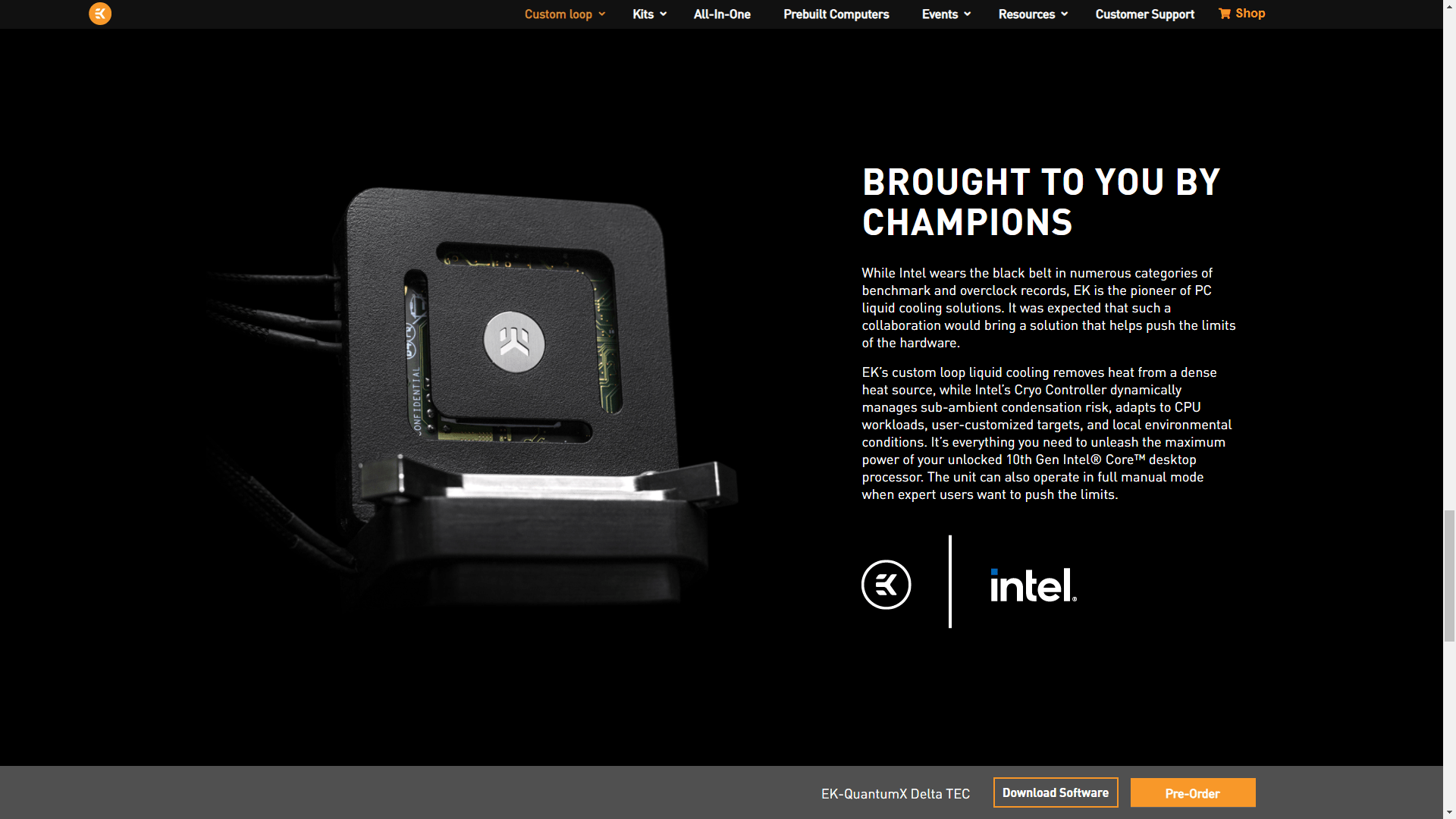
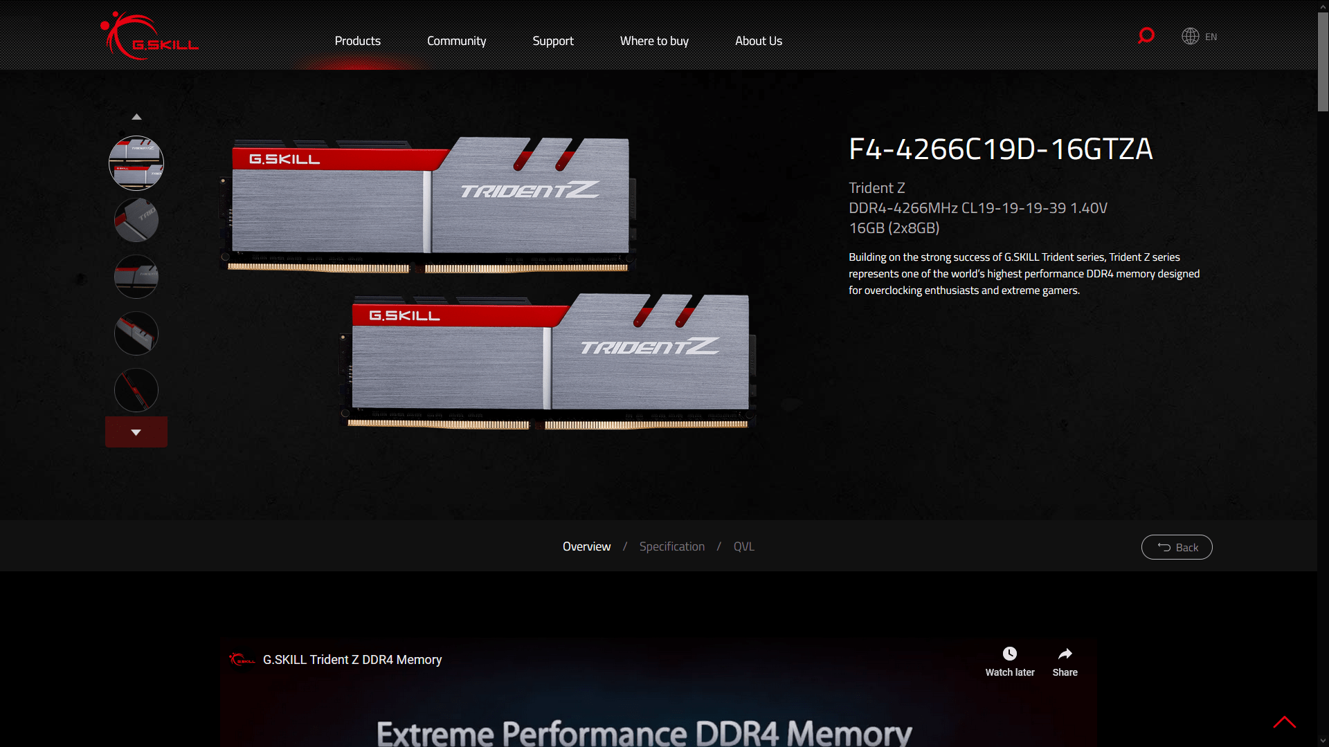
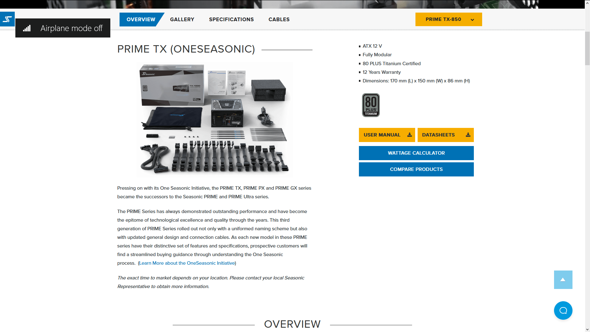
Along with the Intel Core i9-11900K processor and ASUS ROG Maximus XIII Apex motherboard, in this guide, we will be using a pair of G.SKILL Trident Z DDR4-4266 memory sticks, a ROG Strix RTX 2080TI graphics card, a Seasonic Prime 850W Platinum power supply, and the EK-QuantumX Delta TEC with EK-Quantum water cooling. All this is mounted on top of our favorite Open Benchtable.

The cost of the components should be around  540
540
 360
360 1,500
1,500 200
200Intel Core i9-11900K Cryo: Benchmark Software
We use the following benchmark applications to measure performance and ensure system stability.
- SuperPI 4M https://www.techpowerup.com/download/super-pi/
- Geekbench 5 https://www.geekbench.com/
- HWBOT X265 https://hwbot.org/benchmark/hwbot_x265_benchmark_-_4k/
- Cinebench R23 https://www.maxon.net/en/cinebench/
- V-Ray 5 https://www.chaosgroup.com/vray/benchmark
- ROG Realbench V2.56 https://rog.asus.com/rog-pro/realbench-v2-leaderboard/
- 3DMark Night Raid https://www.3dmark.com/
- CS:GO FPS Bench https://steamcommunity.com/sharedfiles/filedetails/?id=500334237
- Final Fantasy XV http://benchmark.finalfantasyxv.com/na/
- Prime 95 https://www.mersenne.org/download/
Intel Core i9-11900K Cryo: Stock Performance
Before we start overclocking let us first have a look at the stock performance of this system. Two important things to note:
One, for the stock performance we leave the Intel Cryo Cooling set to Cryo mode. Intel has improved their software and now you can have the TEC cooler automatically set to Cryo mode when entering the OS. All you have to do is go to the Cryo Cooling desktop try, navigate to Mode and set Cryo. Then navigate to About and check Remember Cryo Mode.
Two, by default the ROG Maximus XIII Apex has unlocked the turbo boost parameters. To check the performance at default settings you must:
- Go to the Xtreme Tweaker menu
- Set ASUS MultiCore Enhancement to Disabled
Then save and exit the BIOS.
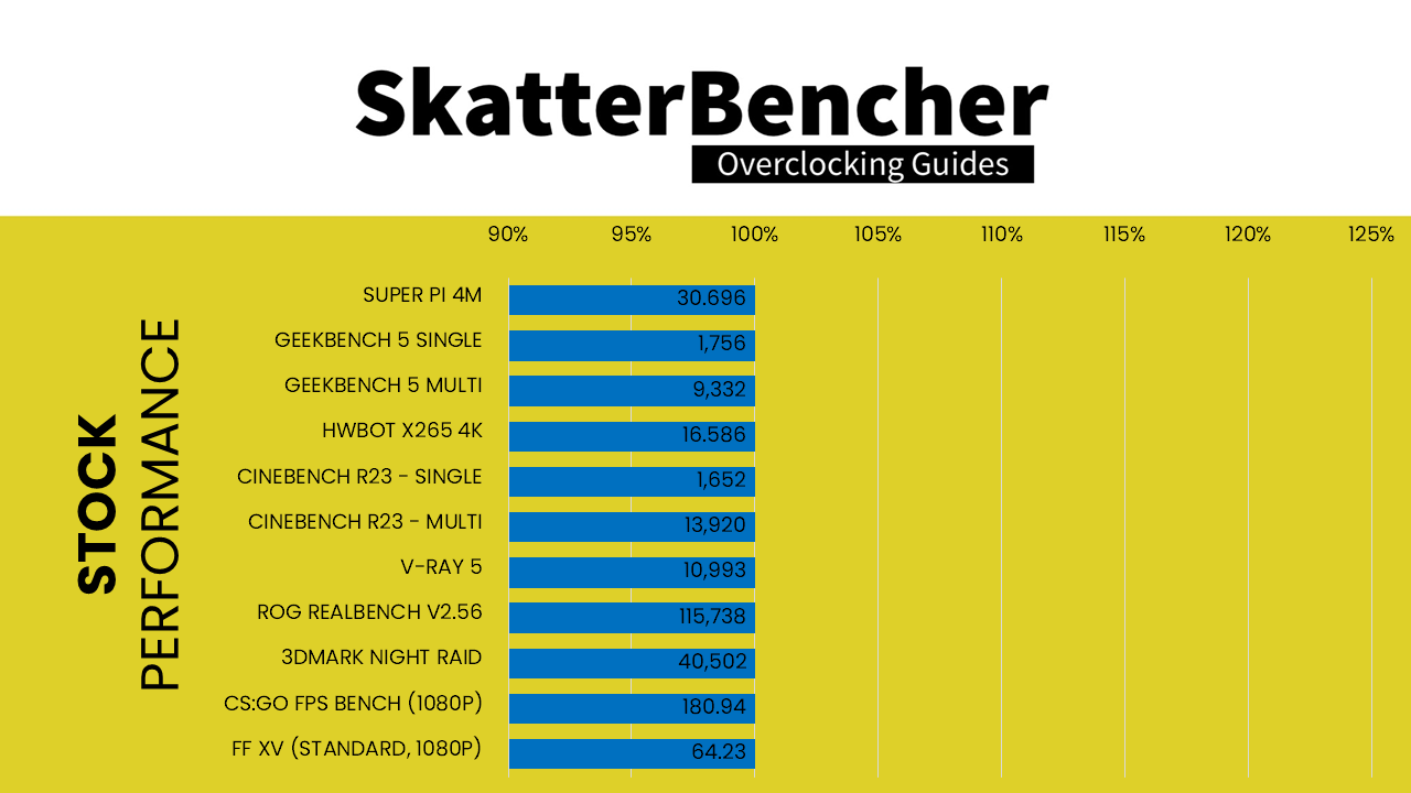
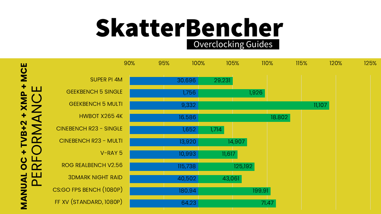
Here is the performance at stock:
- SuperPI 4M: 30.696 seconds
- Geekbench 5 (single): 1,756 points
- Geekbench 5 (multi): 9.332 points
- HWBOT X265 4K: 16.586 fps
- Cinebench R23 Single: 1,652 points
- Cinebench R23 Multi: 13,920 points
- V-Ray 5: 10,993 vsamples
- ROG Realbench V2.56: 115,738
- 3DMark Night Raid: 40,502 points
- CS:GO FPS Bench: 180.94 fps
- Final Fantasy XV: 64.23 fps
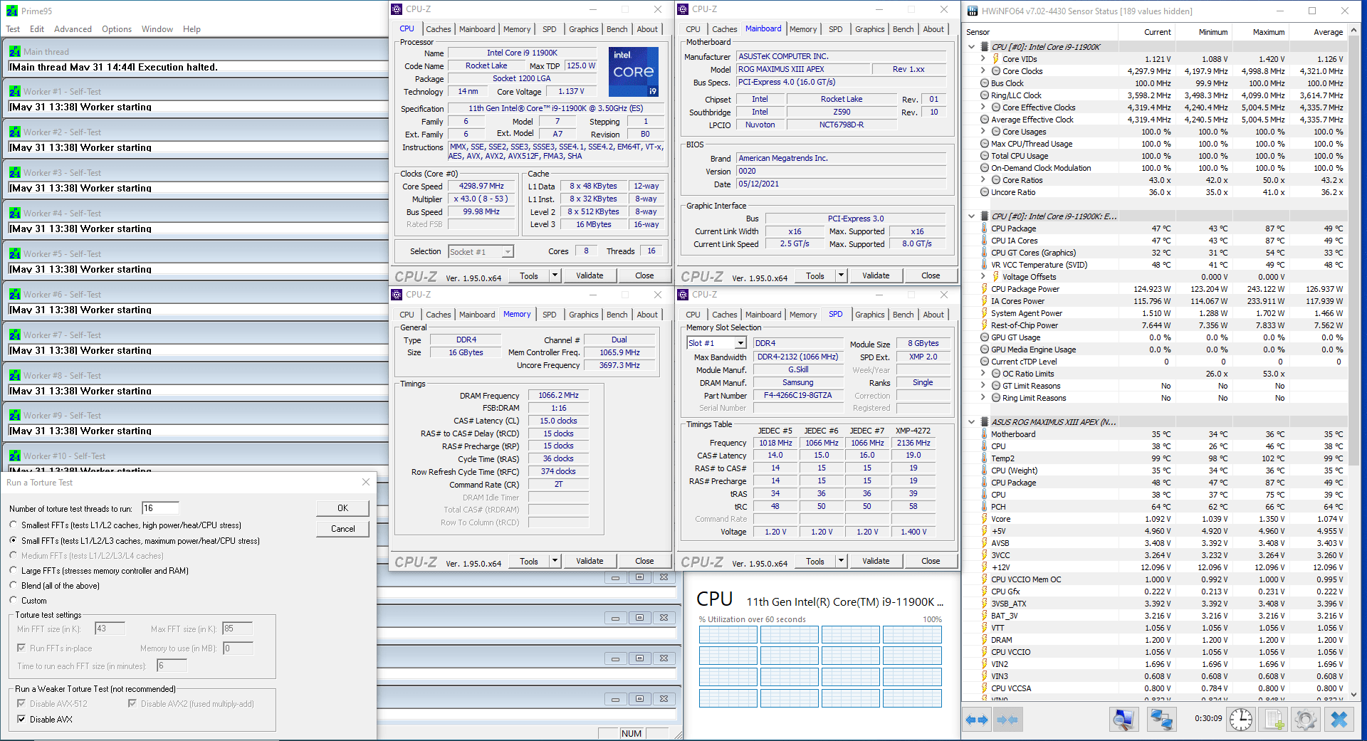
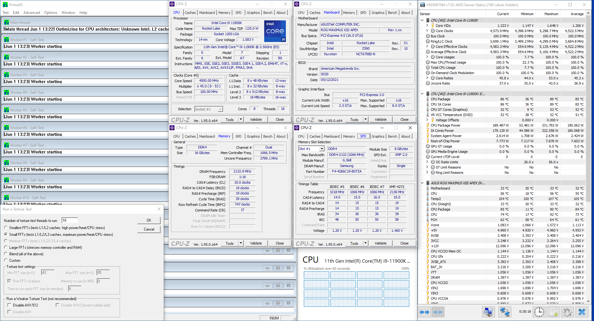
When running Prime 95 Small FFT with AVX enabled, the CPU operates stably at 3836 MHz with 1.029 volts. The average CPU temperature is 54 degrees centigrade, and the average water temperature is 37 degrees centigrade. The average CPU package power is 126.4 watts.

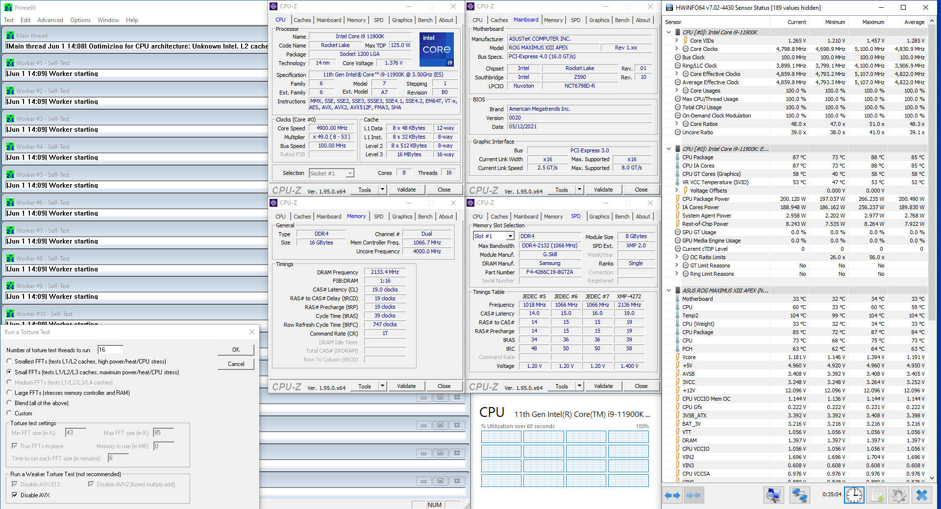
When running Prime 95 Small FFT with AVX disabled, the CPU operates stably at 4321 MHz with 1.074 volts. The average CPU temperature is 49 degrees centigrade, and the average water temperature is 37 degrees centigrade. The average CPU package power is 126.9 watts.
ASUS ROG Maximus XIII Apex BIOS Walkthrough
Before we get started with applying our overclocking settings, I think it is important to go through the BIOS together and explain all the different options and features we will be using for our overclocking strategies. Many of these options will be used in different strategies so it will be useful to thoroughly understand their function and how they can help your overclock.
XMP – Extreme Memory Profile
Intel Extreme Memory Profile, or XMP, is an Intel technology that lets you automatically overclock the system memory to improve system performance.

XMP is an extension to the standard JEDEC specification that allows a memory vendor to program different settings onto the memory stick. The settings include the memory frequency, the memory timings as well as the memory voltage. If you want to know which XMP profiles your memory supports, there are several ways to do it.
- First, if your memory is rated above DDR4-3200, it almost definitely has an XMP profile. That is because the JEDEC standard only goes up to DDR4-3200.
- Second, you can look in your BIOS and find the option to enable XMP. Most, if not all, motherboards support XMP and even allow you to check the specific configuration in BIOS.
- Third, you can use CPU-Z and check the SPD tab. Here you will find the basic XMP profile settings in the Timings Table section.
I almost always run XMP on my systems because it is an incredibly easy and safe way to improve system performance. Do note that some motherboards may adjust CPU memory controller voltages to support extremely high frequency memory.
In this case, our memory kit is rated DDR4-4266 with CAS latency 19 and a voltage of 1.40V. Simply enabling XMP in the BIOS will configure the system.
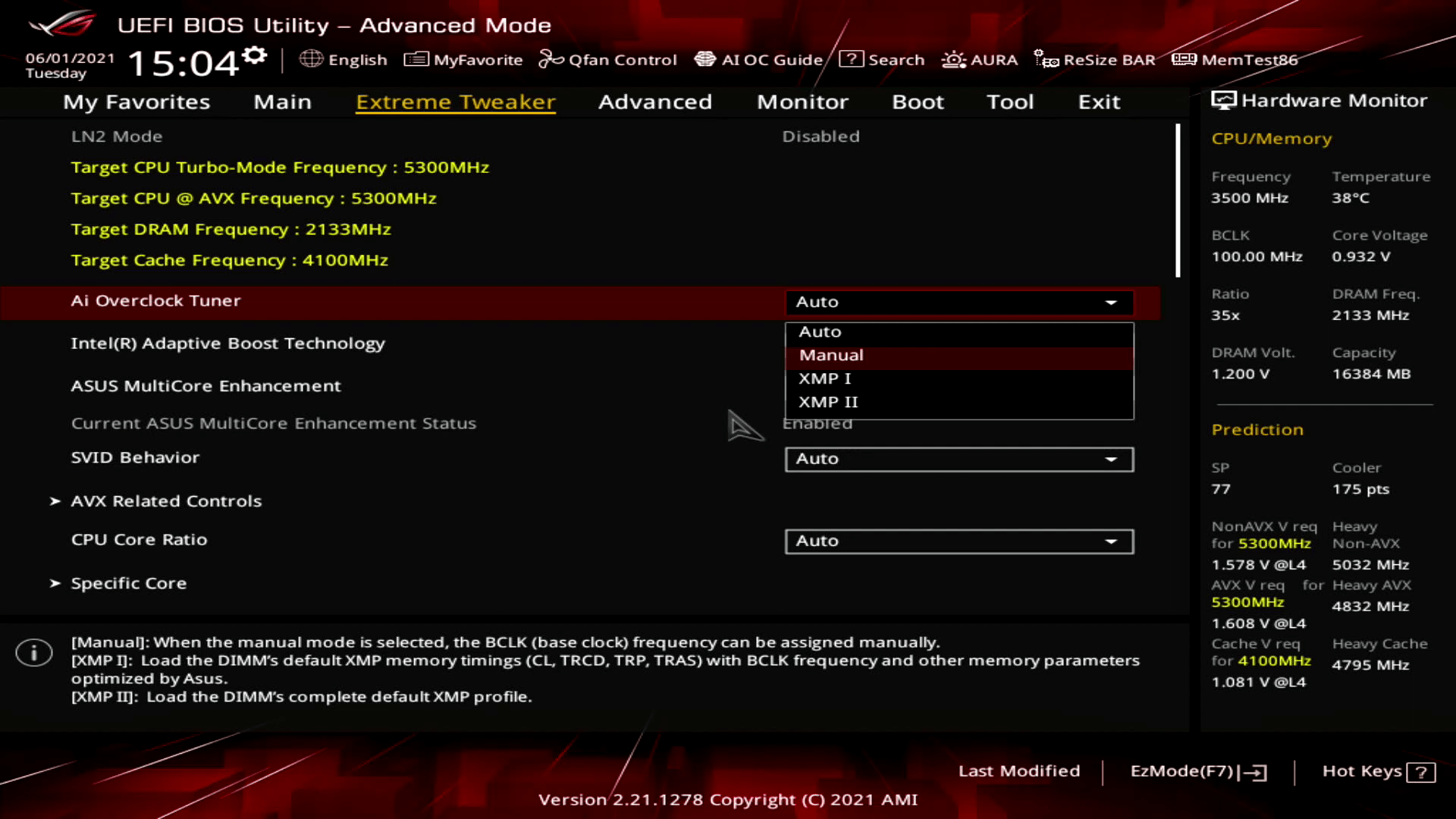
On ASUS BIOSes you usually find two options for setting XMP: XMP I and XMP II
- XMP I only loads the XMP primary memory timings (tCL, tRCD, tRP, tRAS). The board then adjusts the BCLK frequency and other memory parameters according to the motherboard auto-rules.
- XMP II loads the complete XMP profile.
Generally, I would say you should first try the XMP I setting as you may benefit from ASUS specific optimizations for your platform.
ABT – Adaptive Boost Technology
Intel Adaptive Boost Technology was introduced to motherboard partners close to the launch of the 11th generation Intel Core i9 K and KF Rocket Lake CPUs last March. As the technology was not quite ready for the limelight, it was not included in the platform launch but introduced in BIOSes a little after the launch.
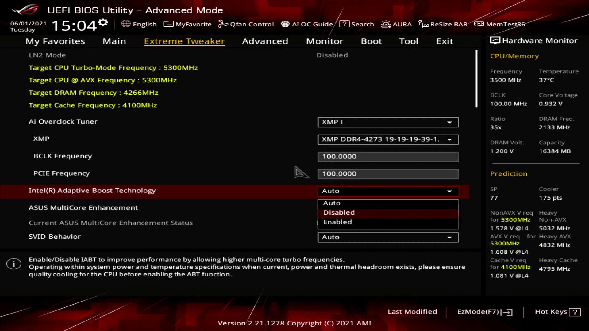
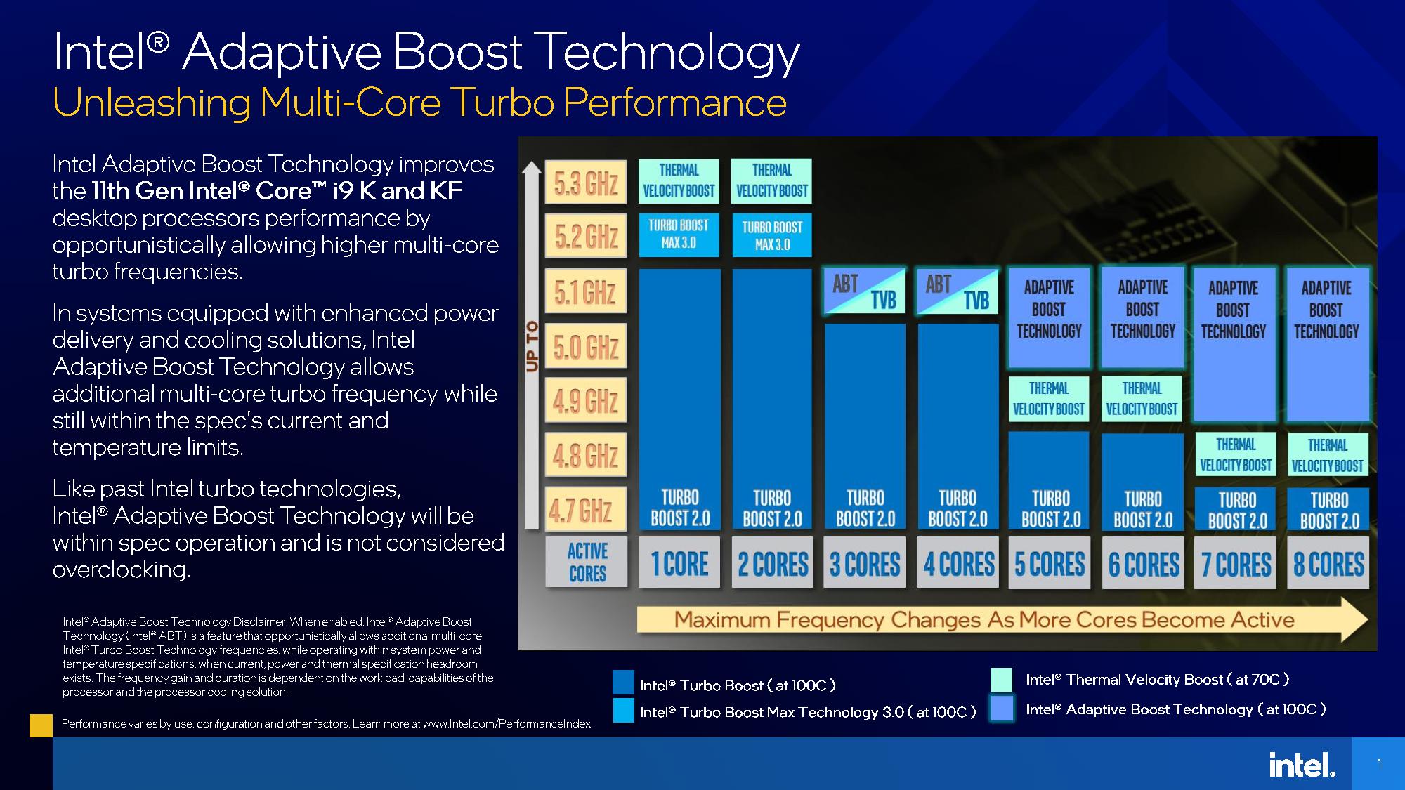
Intel Adaptive Boost Technology opportunistically increases the processor frequency above the Thermal Velocity Boost frequency in systems with adequate power delivery and cooling solutions. ABT allows all cores to hit the maximum Turbo Boost 2.0 frequency even when more than 2 cores are active. Without ABT, the maximum CPU frequency changes as more cores become active.
For example, on the 11900K when 8 cores are active the maximum Turbo Boost 2.0 frequency is 4.7 GHz while with ABT enabled the maximum frequency is 5.1 GHz.
Note that Adaptive Boost Technology is still governed by the Turbo Boost algorithm. So, by default the additional boost will only be available temporarily until the turbo budget has been depleted. However, in combination with technologies like ASUS MultiCore Enhancement you can benefit from up to 400 MHz sustained additional performance.
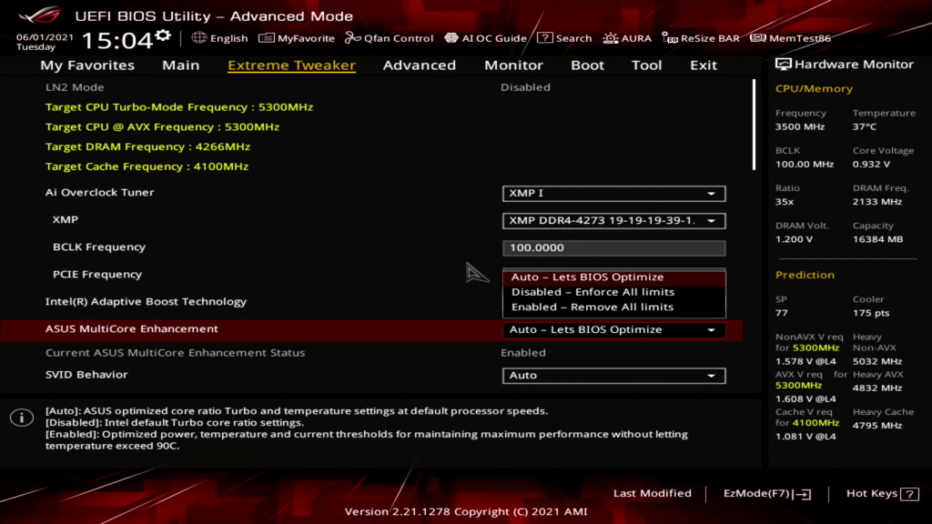
It is also important to mention that while enabling Intel ABT provides higher frequency headroom, it is not considered overclocking as it is still within Intel’s official specification.
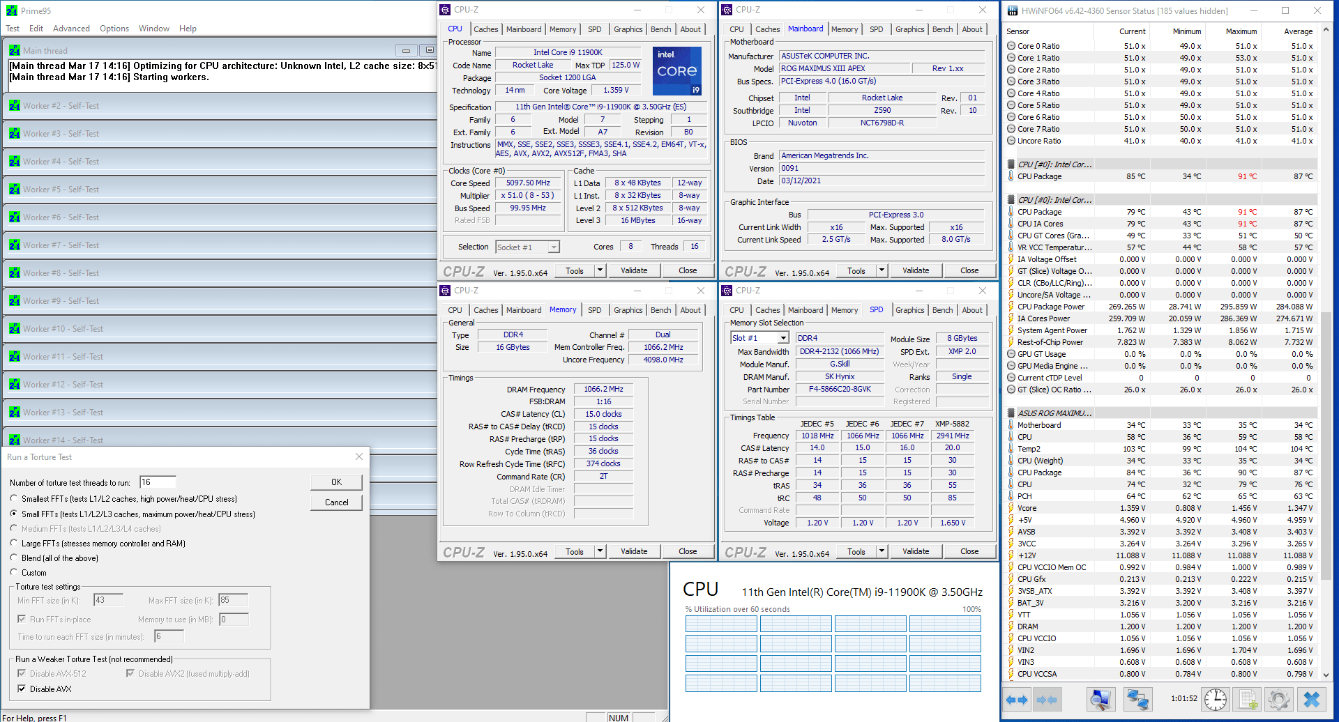
I have not been able to test Adaptive Boost Technology too thoroughly as I got the first BIOSes with support for this feature about a week or two before the Rocket Lake launch. The only result I have is a Prime 95 Small FFTs without AVX result using the EK-Magnitude CPU water block. While the system was perfectly stable at 5.1 GHz all core with a voltage of 1.347V, the average CPU temperature was approaching 90 degrees centigrade, and the average CPU package power was about 285W. For a non-AVX workload – that is quite a lot!
MCE – ASUS MultiCore Enhancement
ASUS MultiCore Enhancement is a single BIOS option that removes all limits constraining the Turbo Boost 2.0 algorithm. Effectively, it allows the CPU to run at maximum turbo boost frequencies indefinitely. On Z590 motherboards, ASUS has enabled this option by default.
For years, hardware reviewers and consumers alike have been very outspoken against motherboard vendors unlocking the Turbo Boost power limits by default. Their key argument is that the CPU is not running at Intel specification. While I understand this argument, I disagree with it.
The Turbo Boost 2.0 algorithm consists of three key parameters. PL1, PL2, and tau. PL1 determines the long-term power consumption, PL2 determines the peak power consumption, and tau is a parameter used for calculating how long the Turbo Boost can be active.
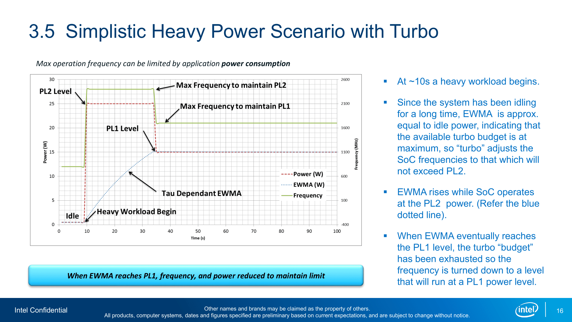
These parameters are chosen to work together with Intel’s minimum specification guidelines for motherboard vendors and third-party cooling solution providers. Effectively, Intel promises the customer a guaranteed minimum performance level even if the customer pairs the CPU with a motherboard that has a minimum specification power delivery design and a cooler that has a minimum specification cooling capacity.
However, we all know that there are plenty of high-quality motherboards with powerful power delivery designs and solutions like custom loop water cooling that can dissipate well over 300W of thermal power.
Therefore, as a performance enthusiast I fully approve of motherboard vendors enabling unlocked power limits by default. Especially on motherboards aimed at customers who will likely purchase high-end cooling solutions. For example, customers who purchase motherboards with the Z-series chipset.
Whether I need 125W or 350W to achieve the maximum performance level is beside the point. It is up to the customer to choose the motherboard and cooling solution that fits their use-case.
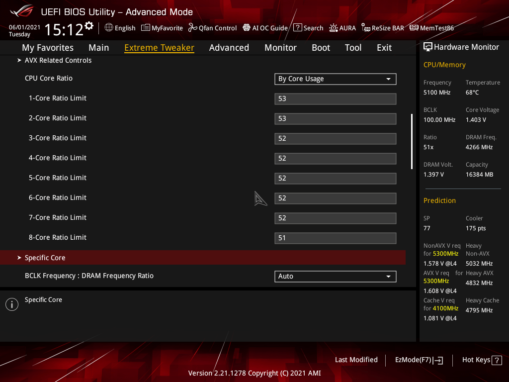
CPU Core Ratio By Core Usage
Generally speaking, on Intel platforms there are two ways to manually configure the CPU ratio: Sync all cores and By Core Usage.
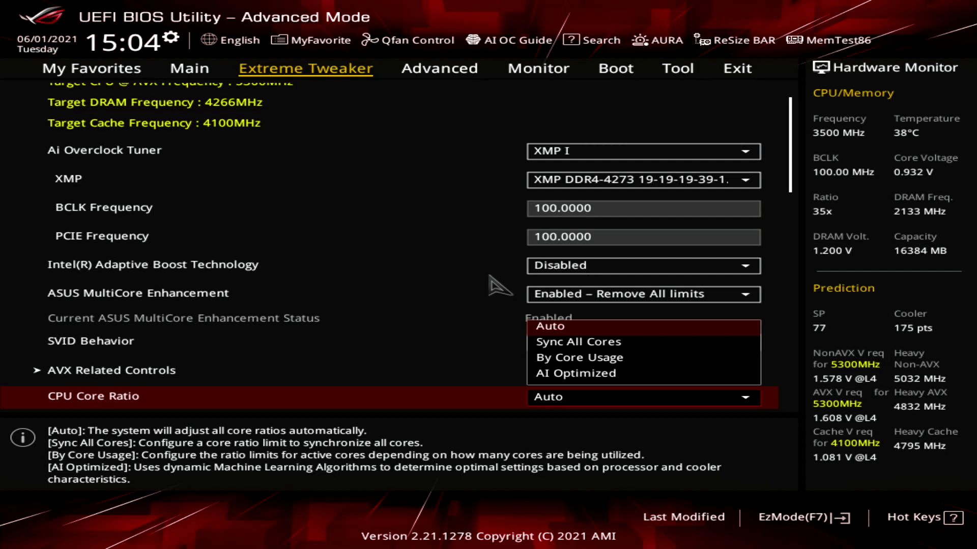
Sync All Cores sets 1 ratio that is applied to all cores. This is very much the traditional way of overclocking.
Of course, back in the day when we only had 1, 2, 3 or four cores, the quality difference between the cores was relatively small. So, there was not that much benefit to max out each core independently.
Nowadays, even mainstream CPUs have up to 16 cores. That means the quality difference between the cores can vary greatly. In addition, the heat produced by 16 cores at full load will be much higher than the heat produced by just a couple of cores at light load. So, if you tune your system for the worst-case scenario, you will miss out on some performance in the most common scenarios.
By Core Usage allows us to configure the overclock for different scenarios ranging from 1 active core to all 8 active cores. This enables us to run some cores significantly faster than others when the conditions are right.
Note that By Core Usage is not the same as configuring each core specifically. When using By Core Usage, we determine an overclock according to the actual usage. For example, if a workload is using 4 cores, then the CPU will determine by itself which cores should execute this workload and will apply our set frequency to those cores.
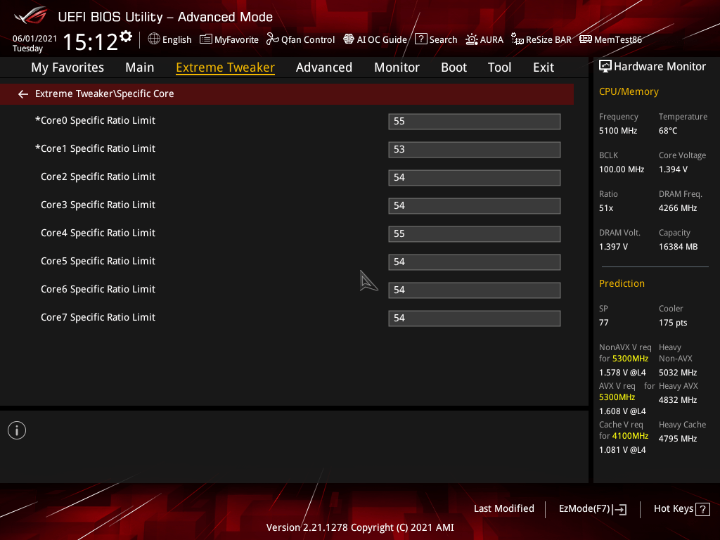
Specific Core Ratio Limit
A big change from previous generations of Intel CPUs on mainstream desktop is that each of the processor cores now has its own PLL. Each core having its own PLL means the processor cores can operate at independent frequencies. Prior to Rocket Lake, on mainstream desktop, all CPU cores of the CPU would run the same CPU ratio.
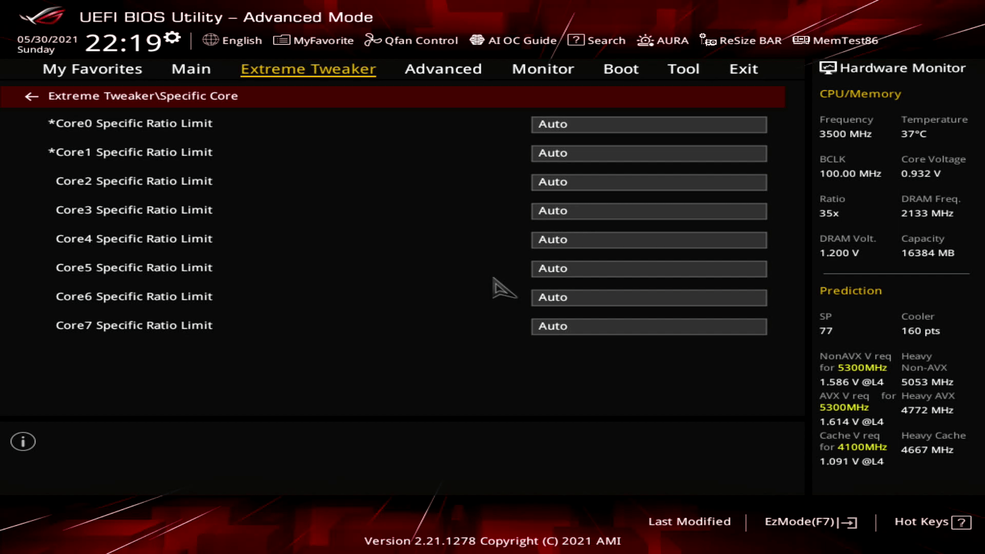
The per core ratio limit allows us to configure each physical core to its own maximum boost ratio. This enables two important new avenues for CPU overclocking.
- First, it allows users to individually overclock each of the cores and find the maximum stable frequency.
- Second, it allows users to set an aggressive by core usage overclock while constraining the worst cores.
Note that while each of the CPU cores now has its own PLL (and its own V/F curve), still only one voltage is applied across all cores. The voltage applied is the highest of all active cores.
OCTVB – Thermal Velocity Boost
In 2018 Intel introduced Thermal Velocity Boost along with the Core i9-8950HK Coffee Lake mobile flagship processor. Thermal Velocity Boost opportunistically increases the clock frequency above the Turbo Boost 2.0 frequencies based on how much the processor is operating below its maximum temperature.
The frequency gain and duration depend on the workload, capabilities of the processor, and the processor cooling solution.
For processors that have Intel® Thermal Velocity Boost enabled, the maximum Core Frequency is achieved when the processor is at a pre-specified temperature or lower and turbo boost budget is available. For the 11900K the pre-specified temperature is 70c.
With the introduction of the Intel Cryo Cooling Technology in 2020, Intel opened up the TVB configuration to motherboard vendors. Obviously, the Cryo Cooling technology exploits the increased overclocking headroom of much lower operating temperatures.
You can use either XTU or, on motherboards that support it, configure Thermal Velocity Boost from the BIOS.
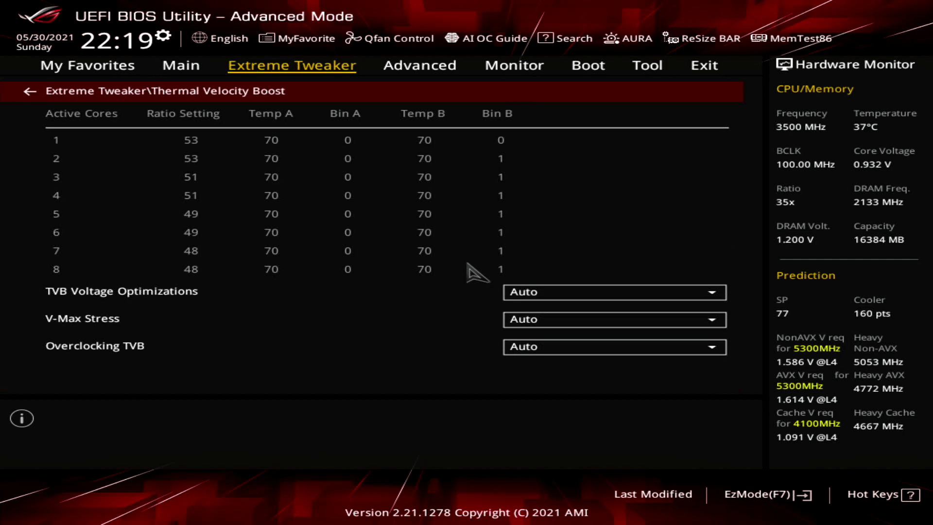
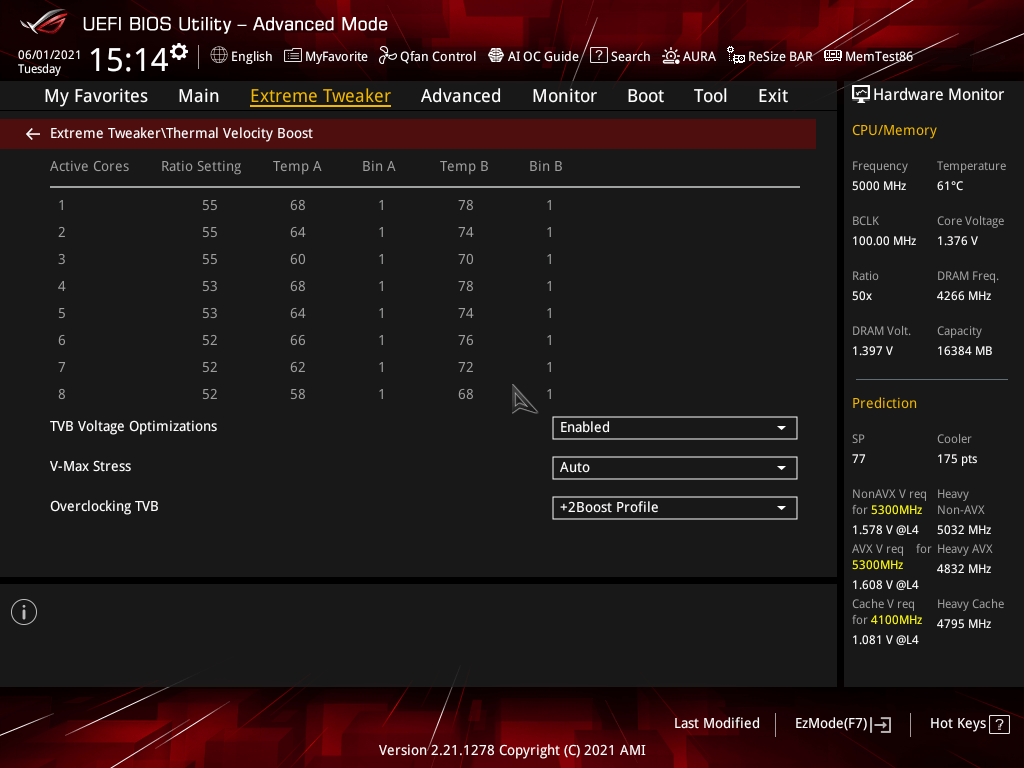
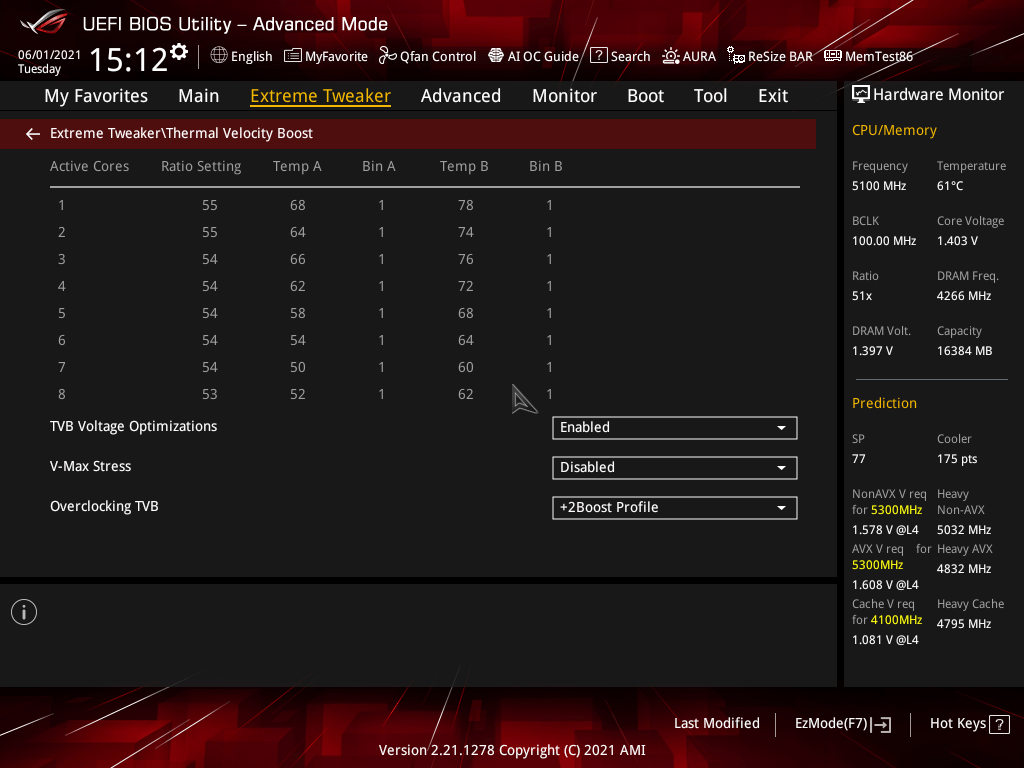
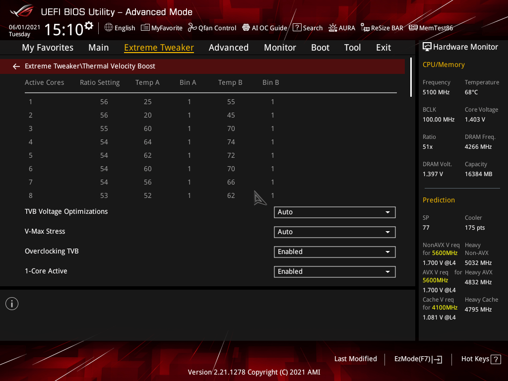
The easiest way to understand the Thermal Velocity Boost configuration is by going from top ratio to bottom ratio. After configuring the settings, save and exit, then go back in the BIOS and back to the TVB submenu. Now you will see a full table of configuration.

The first column lists the count of active cores, going from 1 active core to 8 active cores with the 11900K.
The second column describes the maximum possible ratio for a particular count of active cores. So, in this example, the maximum ratio for 1 core active is 56 and the maximum ratio for 8 cores active is 53. Since we keep a fixed base clock frequency of 100 MHz, this results in respectively 5.6 GHz and 5.3 GHz.
The third column describes the first temperature offset point. When the CPU exceeds this temperature, it will decrease the ratio of the CPU. In my example, when 4 cores are active, and the CPU temperature exceeds 64 degrees then the CPU will decrease the ratio. Similarly, when the temperature exceeds 52 degrees and 8 cores are active, the CPU will also decrease the frequency.
The fourth column describes the ratio offset for the temperature configured in the third column. So, when the CPU temperature exceeds 64 degrees and 4 cores are active, the ratio will decrease by 1. 54 minus 1 equal 53. So, the CPU will run the 4 cores at 5.3 GHz.
The fifth column is an additional temperature offset point. The function is the same as the first temperature offset. While on Comet Lake the ratio offset for temperature B was fixed to 1, on Rocket Lake it is also configurable.
So, in my case, when 2 cores are active the frequency will be 5.6 GHz. However, if the CPU temperature exceeds 20 degrees, then the frequency will be 5.5 GHz. And if the temperature exceeds 45 degrees, the frequency will be 5.5 GHz.
As you can see, the OCTVB function configures the ratio offsets on a by core usage basis. However, as we know Rocket Lake introduced the Per Core Ratio Limit feature. From testing with different tools, it appears that OCTVB also supports Per Core Ratio offsets. The way it negotiates which ratio offset to apply in a given situation is to pick whichever is worse: the ratio offset as determined by the by core usage or the per core ratio limit offset.
The functionality to set OCTVB on a per core ratio limit is not exposed in the Intel documentation and is unlikely to end up in any BIOS. Maybe we will see it pop up in the future.
V/F Point Offset
V/f Point Offset is ASUS’s name for an Intel feature called Advanced Voltage Offset. It is an extension of the Adaptive Voltage Mode that we are familiar with. Advanced Voltage Offset was first introduced with the Comet Lake architecture in 2020. To understand the function and use of this feature, we must first talk about the V/f curve.
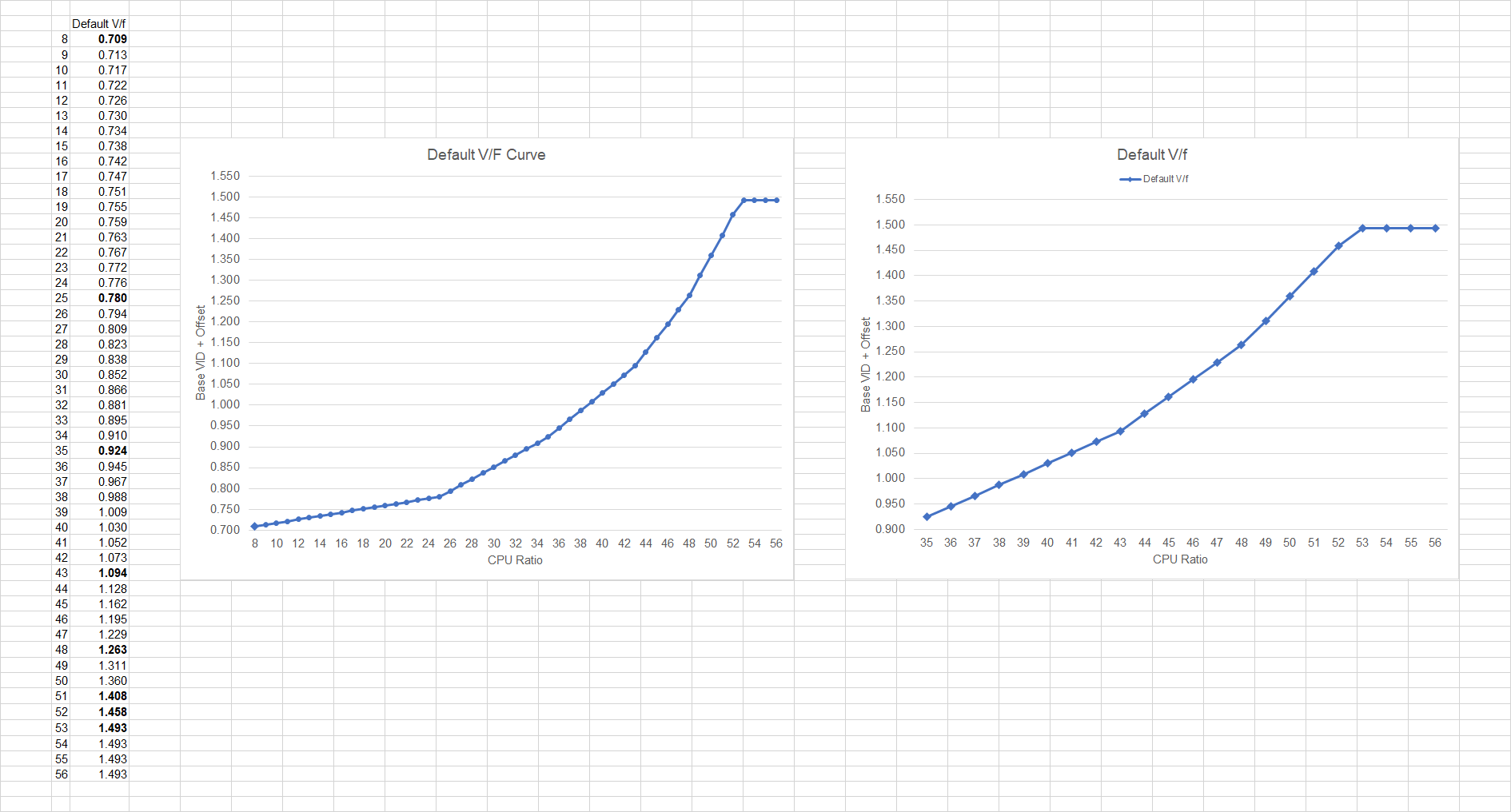
An Intel processor determines a minimum voltage required for each frequency based on a voltage frequency curve. We also call this the V/f curve. It does this for each core separately. This V/f curve is essentially a table that maps the required voltage for a given frequency. This table is generated from multiple factory-fused V/f points using interpolation.
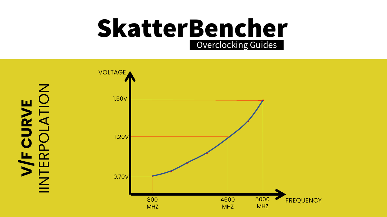
The amount of V/f points is not architectural and can change between SKUs. In other words, specific SKUs can have more or less pre-defined V/F points.
Also, the interpolation method is not architectural and can change at any time.
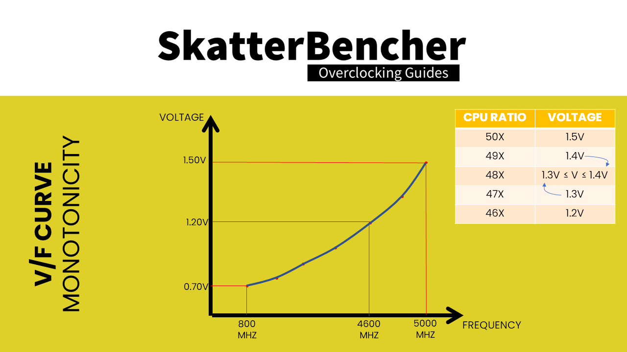
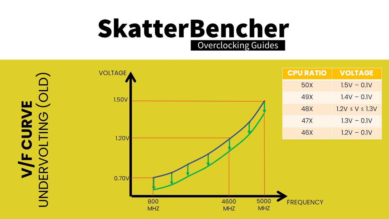
The only requirement for the V/f curve is monotonicity. Following a monotonic function, as a rule the voltage for a given CPU ratio must be equal to or higher than the next lower ratio. So, the voltage for 48X must be equal to or higher than 47X.
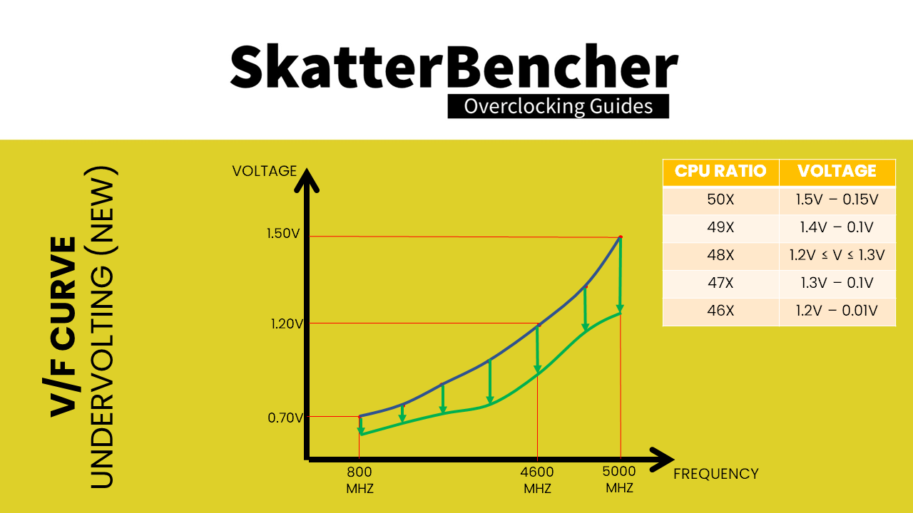
The main purpose of the Advanced Voltage Offset is to provide end users with the ability to under-volt their CPUs at specific parts of the V/f curve. This is fundamentally different than before as prior to this feature the only way to undervolt was to use Adaptive Voltage Mode and offset the entire curve with a single value.
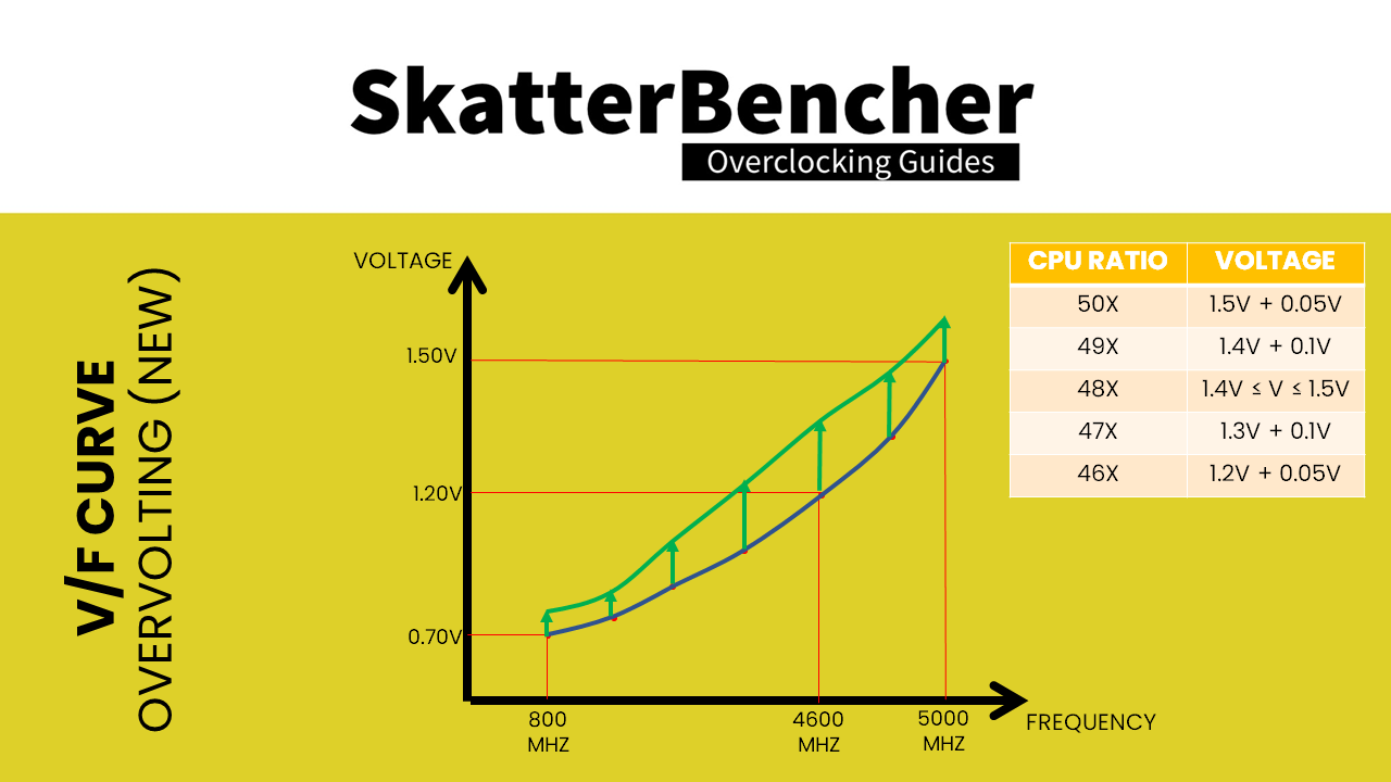
In addition to under-volting, this feature also allows over-volting. This is particularly useful when manual overclocking and when you are trying to increase the maximum frequency.
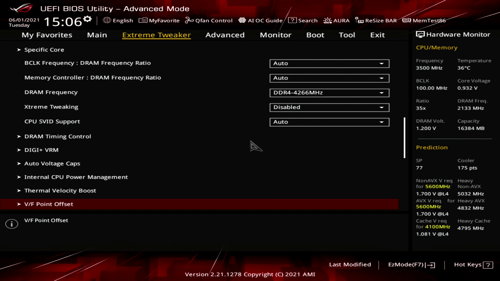
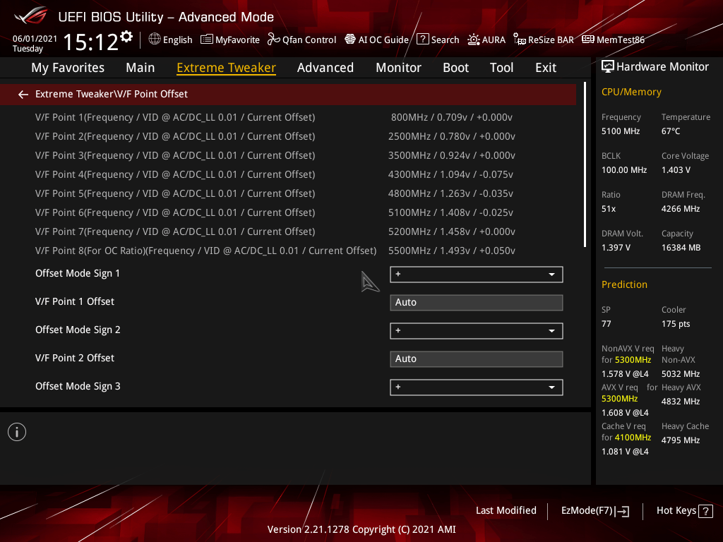
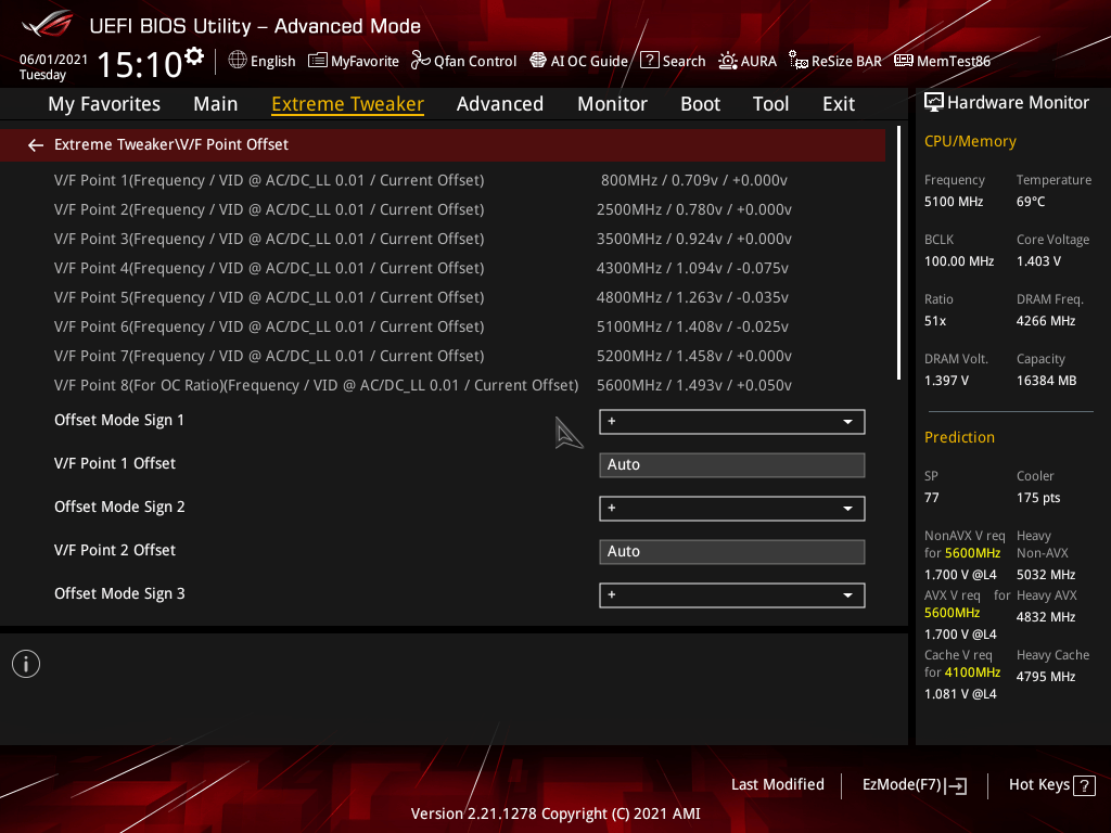
Now that we know the purpose of Advanced Voltage Offset or V/f Point Offset, let us have a look at how it works in the real world. Go into the ASUS ROG BIOS and navigate to the V/F Point Offset submenu in the Extreme Tweaker section.
We find a total of 8 V/f Points. Each V/f Point has three parameters: a specific CPU ratio, a specific voltage, and an offset.
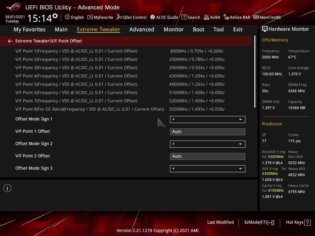
Let us take V/f Point 5 as an example. V/f Point 5 is associated with 4800 MHz, 1.263 volt, and 0 volt offset.
In the ASUS BIOS the frequency is actually the CPU ratio multiplied by the default base frequency of 100 MHz. Keep in mind that Intel’s V/f Curve is based on CPU ratios and not effective frequency. So, it is more correct to say that V/f Point 5 is associated with CPU ratio 48X than 4800 MHz. This is important to know if you decide to play with base clock frequency. But more on that later.
The associated voltage is the base VID and represents the minimum required voltage for a given ratio. For V/f Point 5 the base VID is 1.263V. It is important to understand that this is not the effective voltage for a given CPU ratio at any time.
In Adaptive Voltage Mode, there are three steps to how your system sets the CPU voltage.
- First, the motherboard’s BIOS tells the processor the current loadline characteristics via AC DC loadline values.
- Then, the CPU will request a voltage from the voltage controller based on its own V/f curve using the base VID configuration, adjusting for the current loadline characteristics, as well as any other voltage offsets.
- Finally, the voltage that reaches the CPU is the requested voltage minus any undershoot or overshoot from the VRM loadline.


To put it in formulas:

![\[ Requested VID = Base VID + Offset + (AC Loadline x Current) +AVX Guardband - TVB Vopt \]](https://skatterbencher.com/wp-content/ql-cache/quicklatex.com-dd3a7771452623da1deaacba01bd6aaa_l3.png "Rendered by QuickLaTeX.com")
![\[ Readback VID = Requested VID - (DC Loadline x Current) \]](https://skatterbencher.com/wp-content/ql-cache/quicklatex.com-a9ef10ffa666514af7567a40353fef4d_l3.png "Rendered by QuickLaTeX.com")
![\[ Effective Voltage = Requested VID - Vdroop \]](https://skatterbencher.com/wp-content/ql-cache/quicklatex.com-5cf4ec2ba63feca7a0e9c020d0820f5d_l3.png "Rendered by QuickLaTeX.com")
Where
- Base VID is determined by your specific CPU V/f curve
- Offset is determined by the user set adaptive voltage offset
- AC/DC Loadline is determined by the motherboard design
- AVX Guardband is determined by whether AVX workload is present and AVX guardband is enabled
- TVB Vopt is determined by whether Thermal Velocity Boost is available and Voltage Optimization function is enabled
- Vdroop is determined by the motherboard VRM and system load
If the readback VID is lower than the Base VID, the CPU will dynamically increase requested VID.
The AC DC loadline characteristics are basically a way for the motherboard to inform the CPU about its design. Based on the specific design, the CPU will factor in a certain voltage droop when requesting a VID. Voltage droop is the decrease of voltage when a core goes from idle to full load.
The AVX voltage guardband ensures that the effective voltage during an AVX workload stays within the required range at all times to ensure stability. What is new with Rocket Lake CPUs is that users are given an option to change the voltage guard-band when running AVX2 and AVX512 instructions using the Voltage Guard-band Scale Factor.
Thermal Velocity Boost Voltage Optimization is a little-known feature of Thermal Velocity Boost. When enabled, the CPU will gradually decrease the voltage if sufficient thermal headroom is available. There is no detailed documentation on how it works exactly, but from testing and empirical evidence it looks the voltage reduction is based on the difference between the actual CPU temperature and TjMax.
The VRM loadline setting determines how much the output voltage increases or decreases when the CPU goes from a low load to a high load or vice versa. Simply put, a big undershoot or big overshoot can result in an unstable system. So VRM loadline helps to mitigate this problem. You can check out the article titled VRM Load-Line Visualized by ElmorLabs for more information.
Okay, back to our V/f Point Offsets.
The last parameter of the V/f Point Offset is the offset itself. This can be either negative or positive and ranges from 0mV to 500mV. The offset adjusts the base VID. So, if we use a negative offset of 100mV for V/f Point 5 the base VID for CPU ratio 48X would be 1.263V minus 0.1V equals 1.163V. Pretty straightforward!
But, Pieter, what about the CPU ratios in between the V/f Points? Great question!
As I explained before, Adaptive Voltage Mode and its extension Advanced Voltage Offset utilizes interpolation to determine the final V/f Curve. So, assuming that all the factory-fused V/f Points are exposed in this sub-menu, the base VID for CPU Ratio 45X will be somewhere in between the 1.094V associated with 43X and 1.263V associated with 48X.
We do not know the exact interpolation method so we cannot accurately calculate this value. However, since we know the V/f Curve requires monotonicity, we can estimate it using a straight-line approach. Offsetting either endpoint of this straight-line will also affect the points on this line. So, if we want to reduce the base VID for 45X, we can use a negative offset for either V/f Point 4 (43X), or V/f Point 5 (48X), or both.
Okay, two more things. I promise.
V/f Point 8 is associated with what is called the “OC ratio”. It is the highest point on the V/f Curve and is usually associated with the default maximum turbo ratio. For the 11900K, that’s 53X. When overclocking beyond the maximum ratio, we actually just change this V/f Point.
In our example, the V/f Point 8 has been adjusted to CPU ratio 55X, uses the base VID of 53X, and has a positive offset of 50mV.
Interestingly, V/f Point 8 is the only point on the V/f curve where you can directly adjust the base VID. We do this by simply setting the Adaptive Voltage in the BIOS. Of course, this base value must be equal to or higher than the previous V/f point which is 1.458V for 52X.
Also, maybe important to highlight is that when people use Adaptive Voltage Mode and manually set that voltage, this only affects the voltage for the CPU ratios higher than the default maximum CPU ratio minus one.
Again, the base VID for CPU ratios between 52X and 55X will be determined by interpolating between 1.458V and, in this case, 1.543V. (base VID plus offset)
Last thing. A little earlier I said that the V/f Point is associated with a CPU ratio and not an effective frequency. This is especially important to know when you are doing BCLK frequency overclocking.
For example, let us say the factory-fused base VID for 46X is 1.20V and the base VID for 48X is 1.26V. If we use a CPU ratio of 46X and a BCLK of 104.4 MHz, the resulting frequency is about 4800MHz. But the base VID will still be 1.20V as it is determined by the set CPU ratio! So, the system would likely be unstable.

For avoid this we can use another Intel overclocking knob called BCLK Aware Adaptive Voltage.
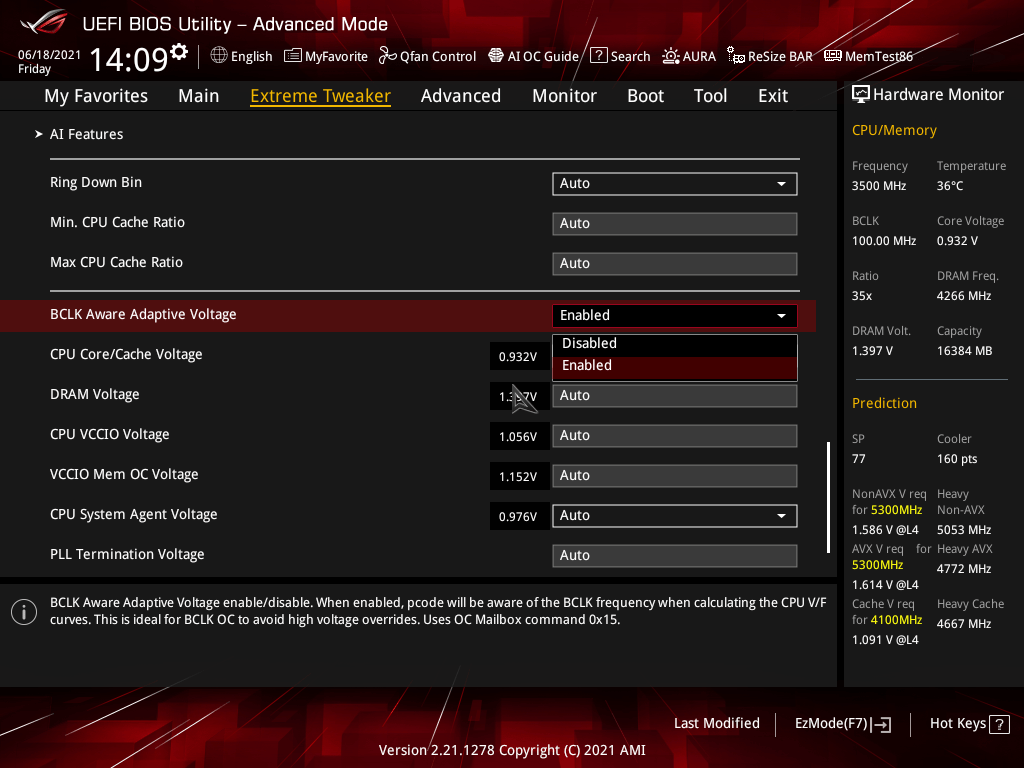
This feature was introduced along with the Kaby Lake processers all the way back in 2016. When enabled, the processor scales its voltage calculations for all the V/f power domains and produces voltage based on frequency as opposed to the multiplier. The V/f power domains include the CPU cores, the Ring, and the integrated graphics. Similar to the interpolation, we know this feature exists and what it does, but we do not know the exact algorithm for this scaling.
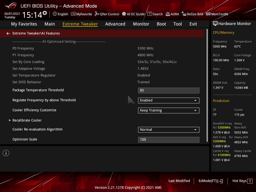
AI Overclocking
For many years board vendors have tried to implement automatic overclocking features in their BIOS for simpler performance enhancement. This has always been a mixed bag as most of the preset OC profiles are overly optimistic in frequency target or overly generous with the voltage selection. So often you would end up with a slightly unstable or overheating system.
ASUS AI overclocking uses a different strategy. Instead of working with preset profiles, the system will monitor the CPU and cooling system throughout an initial phase of testing, then based on its findings predict the optimal settings. The system will then automatically guide the overclocking process and adjust voltages and frequency to match your cooling system.
The better your cooling, the higher your AI overclock.
There are three steps to enabling AI overclocking. First, reset the BIOS to default settings. Then, reboot and enter the operating system. Run a couple of heavy workloads such as Prime95, Realbench or Intel XTU for 10 to 30 minutes. Then return to the BIOS and enter the AI OC Guide menu from the top. Make sure to read through the explanation and when ready simply click Enable AI.
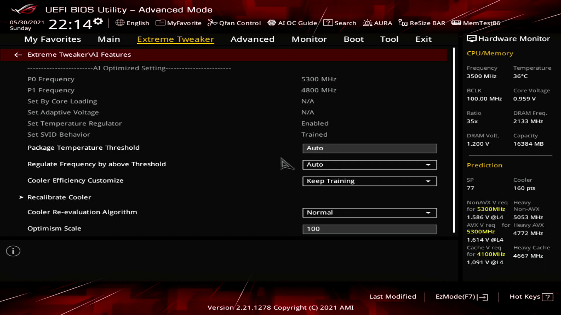
Package Temperature Threshold
I briefly covered this feature in the Rocket Lake launch video.
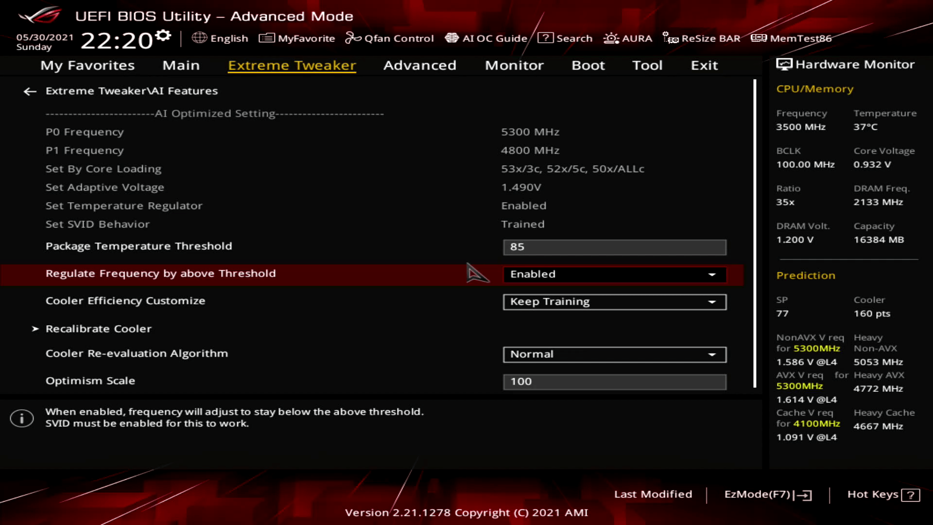
In essence, this feature allows you to configure a maximum temperature for the CPU. The ASUS motherboard will track the CPU temperature during operation and once the temperature exceeds your target temperature, the CPU frequency will be reduced. It does this not directly by adjusting the CPU ratio, but rather by adjusting the Turbo Boost power limit parameters. By lowering the power limits, the Intel CPU will adjust the CPU ratio down on its own.
By default, ASUS has enabled this setting on the Z590 motherboards as they also enabled MultiCore Enhancement. The default setting for the Maximus XIII series motherboards is 90 degrees centigrade. In the ASUS ROG BIOS, you can adjust the package temperature threshold in the Extreme Tweaker AI Features submenu.
For this overclocking guide we set this value to 85 degrees centigrade for all our overclocks.
Q-Fan Configuration
Q-Fan is a feature that has been around since the early 2000s on ASUS motherboards. Its main function is to regulate the system fans according to how taxed the system is. Today’s implementation of Q-Fan is much more advanced than it was twenty years ago.

I think this is a section of the BIOS which is used by many enthusiasts to manually set up the fan behavior. For this guide we will only use 1 specific feature.
We configure the Chassis Fan 2 to follow the T_Sensor. We connect a temperature sensor to the header near the bottom of the board and put the sensor in our water loop. We do this to address a specific issue with the TEC cooling in unregulated mode.
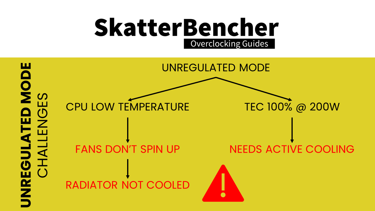
By default, the system fans are mapped against the CPU temperature. When we set the Cryo Cooling to Unregulated mode, the CPU temperature will be exceptionally low in idle. Therefore, the radiator fans will not spin up and this the radiator will not be actively cooled.
However, in Unregulated mode the TEC is working at full power and must be actively cooled. In our case, the Delta TEC adds 200W of load in the water loop.
So, this creates a problem. One the one hand, we are adding heat in the loop because of unregulated mode and on the other hand the fans are not spinning up also because of unregulated mode. This can potentially get out of hand.
With our configuration we ensure that the water temperature is monitored in unregulated mode and action is taken in case the temperature increases too much.
Now, let us try our first overclocking strategy.
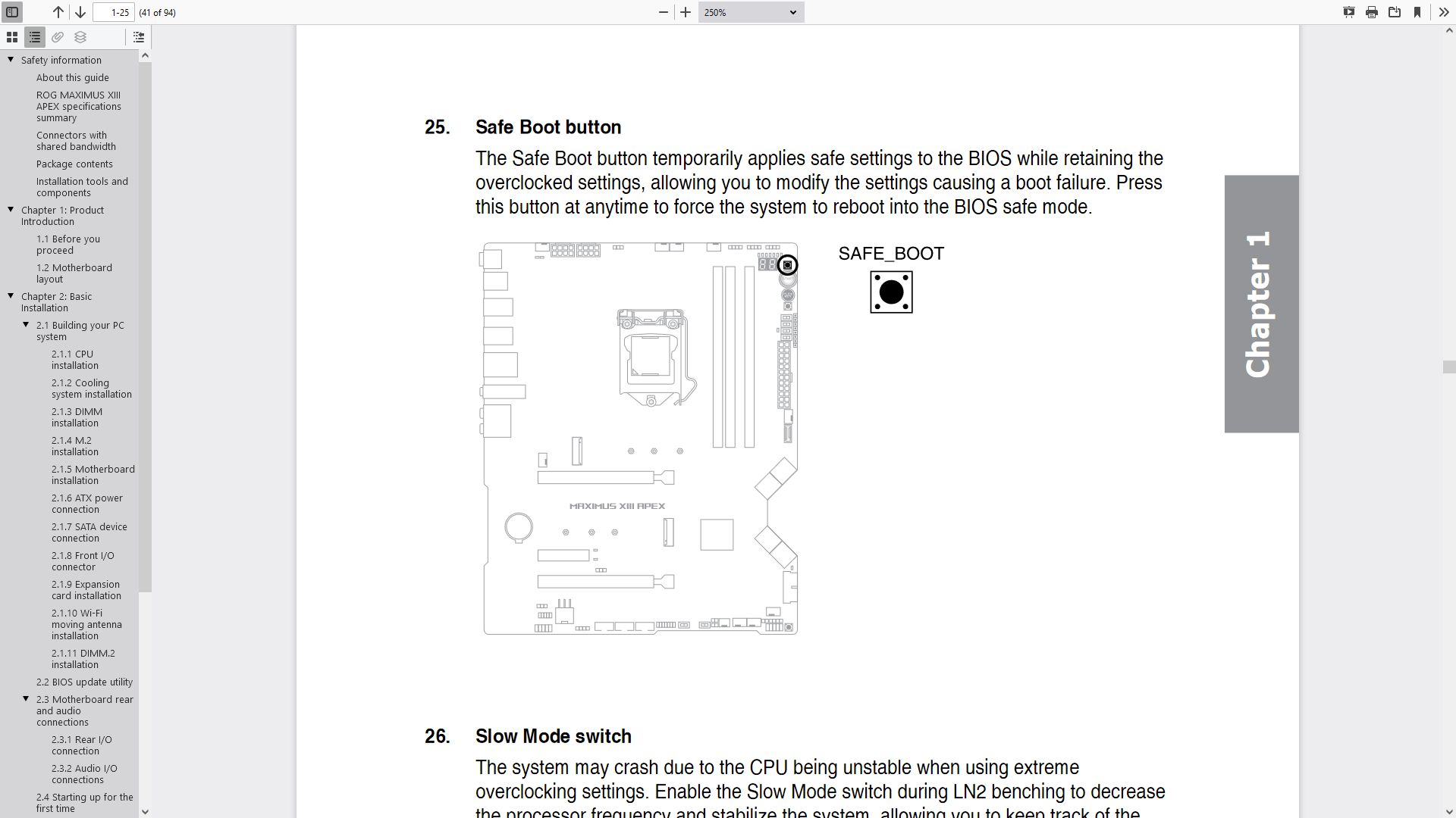
However, before we get started make sure to locate the Safe Boot Button on your motherboard. In case your system fails to boot up after you configured your settings, pressing this button will force the system to boot at default settings while retaining your BIOS configuration. So, you can return to the BIOS easily and make the necessary adjustments.
OC Strategy #1: ABT + XMP + MCE
In our first overclocking strategy we simply unlock some of the performance constraints by enabling Intel ABT, Intel XMP, and ASUS MCE.
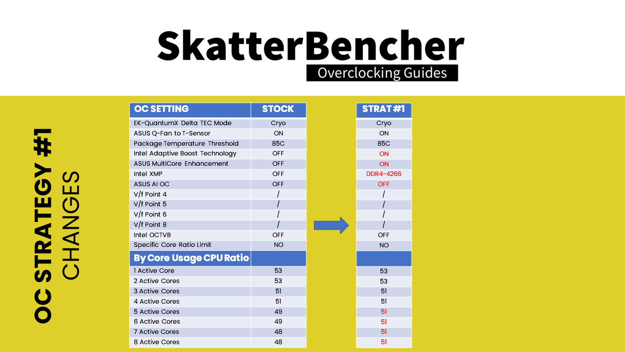
There are 3 main differences between the default configuration and this overclocking strategy.
- First, Intel ABT allows the CPU to boost to 5.1 GHz when all cores are active whereas the default configuration only allows 5.1GHz for up to 4 active cores and up to 4.8GHz with 8 active cores.
- Second, Intel XMP increases the memory frequency to DDR4-4266 up from the stock speed of DDR4-2133. Do note that this will also enable Gear 2 mode.
- Third, ASUS MCE unlocks the Turbo Boost parameters allowing for essentially unlimited time at the highest performance levels.
Upon entering the BIOS
- Go to the Extreme Tweaker menu
- Set AI Overclock Tuner to XMP I
- Set Intel Adaptive Boost Technology to Enabled
- Set Asus MultiCore Enhancement to Enabled – Remove All Limits
- Enter the AI Features submenu
- Set Package Temperature Threshold to 85
- Set Regulate Temperature Threshold to Enabled
- Go to the Monitor menu
- Enter the Q-Fan Configuration submenu
- Enter the Chassis Fan Configuration submenu
- Set Chassis Fan Profile to Manual
- Set Chassis Fan Q-Fan Source to T_Sensor
- Set Chassis Fan Lower Temperature to 30
- Set Chassis Fan Middle Temperature to 35
- Set Chassis Fan Upper Temperature to 40
- Set Chassis Middle Duty Cycle to 60
Then save and exit the BIOS.
We re-ran the benchmarks and checked the performance increase compared to the default operation.
- SuperPI 4M: 0.98%
- Geekbench 5 (single): 0.85%
- Geekbench 5 (multi): 15.55%
- HWBOT X265 4K: 12.23%
- Cinebench R23 Single: 1.27%
- Cinebench R23 Multi: 7.06%
- V-Ray 5: 4.68%
- ROG Realbench V2.56: 5.66%
- 3DMark Night Raid: 6.27%
- CS:GO FPS Bench: 2.16%
- Final Fantasy XV: 6.60%
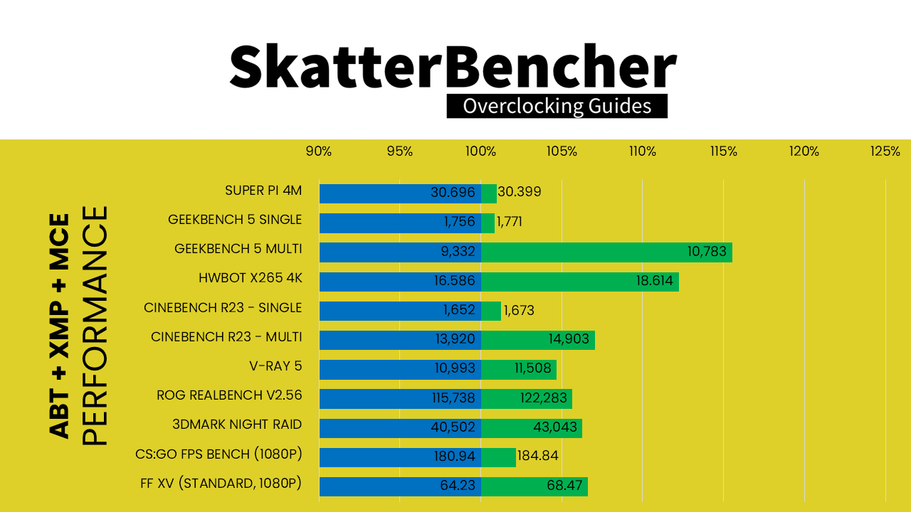
As expected, compared to default settings we see the largest performance gains in multi-threaded and 3D benchmark workloads. This is to be expected since the default configuration limits the time our CPU can be in full Turbo Boost, whereas enabling MCE lifts that restriction.
When running Prime 95 Small FFT with AVX enabled, the CPU operates stably at 4262 MHz with 1.132 volts. The average CPU temperature is 85 degrees centigrade, and the average water temperature is 37 degrees centigrade. The average CPU package power is 188.2 watts.
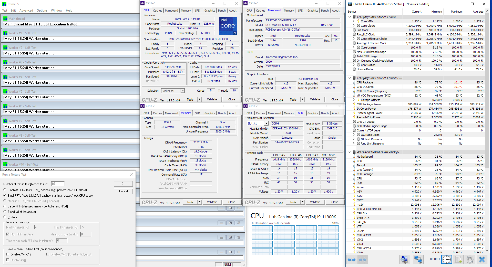
When running Prime 95 Small FFT with AVX disabled, the CPU operates stably at 4736 MHz with 1.204 volts. The average CPU temperature is 85 degrees centigrade, and the average water temperature is 37 degrees centigrade. The average CPU package power is 202.2 watts.

Now let’s start with the actual overclocking!
OC Strategy #2: AI OC + OCTVB+1 + XMP + MCE
In our second overclocking strategy we no longer use Intel ABT to define the maximum CPU frequency and instead let the ASUS AI do its thing. In addition, we also use the ASUS built-in OCTVB profile to increase the frequency when the temperature is low enough, benefiting from our Delta TEC cryo cooler.
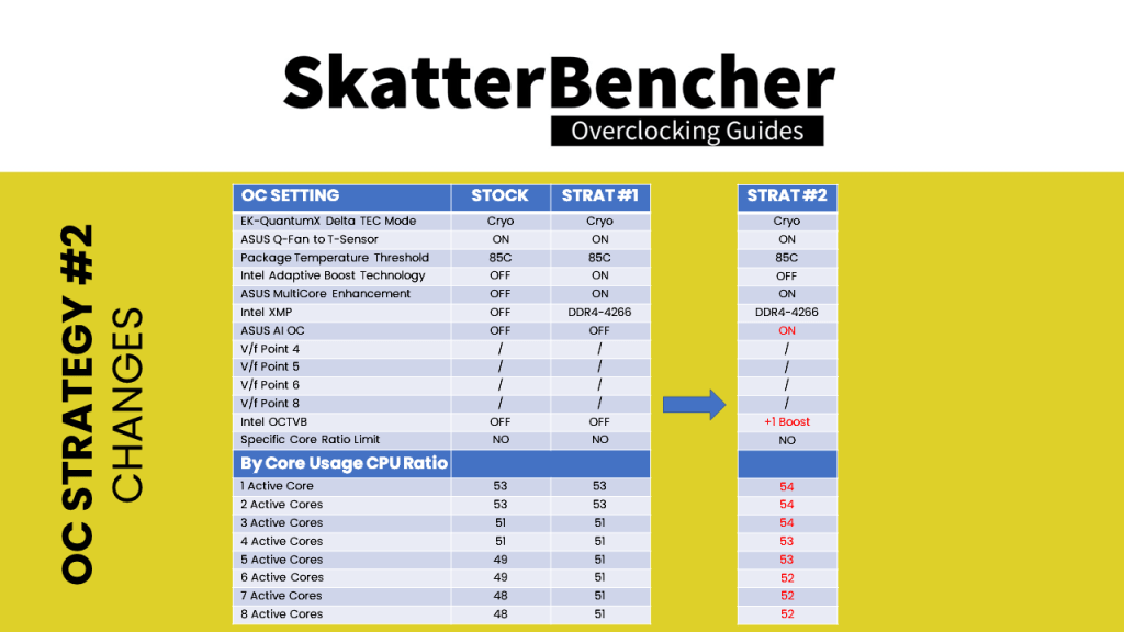

The main difference between strategy 2 and strategy 1 is the increase of maximum CPU frequency across the board. The 1 active core can now boost up to 5.4 GHz and 8-core active can boost up to 5.2 GHz.
Upon entering the BIOS
- Go to the Extreme Tweaker menu
- Set AI Overclock Tuner to XMP I
- Set Intel Adaptive Boost Technology to Disabled
- Set Asus MultiCore Enhancement to Enabled – Remove All Limits
- Set CPU Core Ratio to AI Optimized
- Enter the Thermal Velocity Boost submenu
- Set Overclocking TVB to +1Boost Profile.
- Leave the Thermal Velocity Boost submenu
- Enter the AI Features submenu
- Set Package Temperature Threshold to 85
- Set Regulate Temperature Threshold to Enabled
- Go to the Monitor menu
- Enter the Q-Fan Configuration submenu
- Enter the Chassis Fan Configuration submenu
- Set Chassis Fan Profile to Manual
- Set Chassis Fan Q-Fan Source to T_Sensor
- Set Chassis Fan Lower Temperature to 30
- Set Chassis Fan Middle Temperature to 35
- Set Chassis Fan Upper Temperature to 40
- Set Chassis Middle Duty Cycle to 60
- Enter the Chassis Fan Configuration submenu
Then save and exit the BIOS.
We re-ran the benchmarks and checked the performance increase compared to stock operation.
- SuperPI 4M: 3.20%
- Geekbench 5 (single): 7.18%
- Geekbench 5 (multi): 16.22%
- HWBOT X265 4K: 12.5%
- Cinebench R23 Single: 2.12%
- Cinebench R23 Multi: 7.68%
- V-Ray 5: 4.99%
- ROG Realbench V2.56: 8.85%
- 3DMark Night Raid: 4.26%
- CS:GO FPS Bench: 4.95%
- Final Fantasy XV: 10.49%
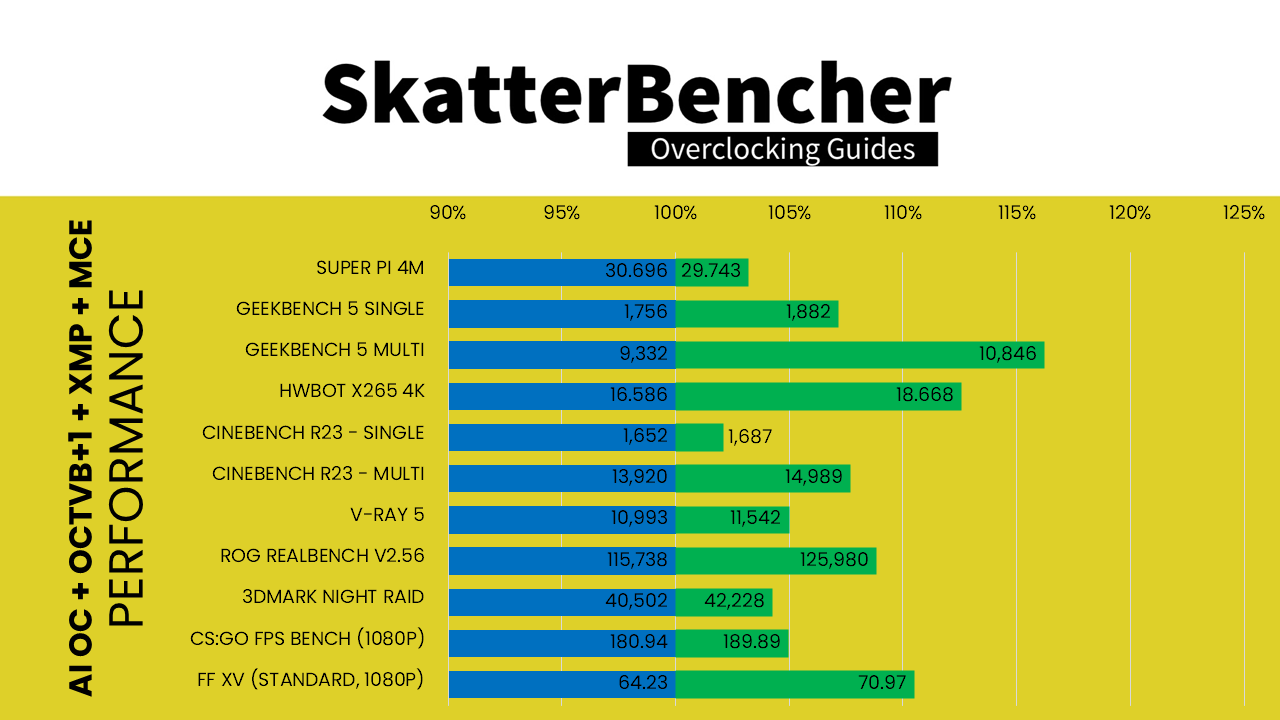
As expected, we see performance gains across the board as both single core and all core maximum frequencies have increased over default configuration.
When running Prime 95 Small FFT with AVX enabled, the CPU operates stably at 4376 MHz with 1.118 volts. The average CPU temperature is 85 degrees centigrade, and the average water temperature is 37 degrees centigrade. The average CPU package power is 186.6 watts.

When running Prime 95 Small FFT with AVX disabled, the CPU operates stably at 4778 MHz with 1.197 volts. The average CPU temperature is 85 degrees centigrade, and the average water temperature is 37 degrees centigrade. The average CPU package power is 199.6 watts.

OC Strategy #3: AI OC + OCTVB+2 + XMP + MCE
Our third strategy is not really that much different from our second strategy. We again let the AI do its thing when it comes to setting the CPU frequency. However, we go a little more aggressive with the OCTVB and enable the +2-boost profile.
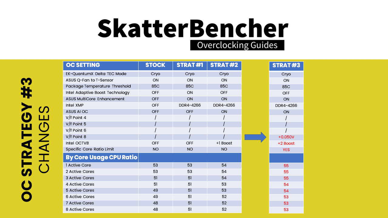


The main difference between strategy 3 and strategy 2 is that the maximum frequency for each count of active cores is increased by 1 ratio.
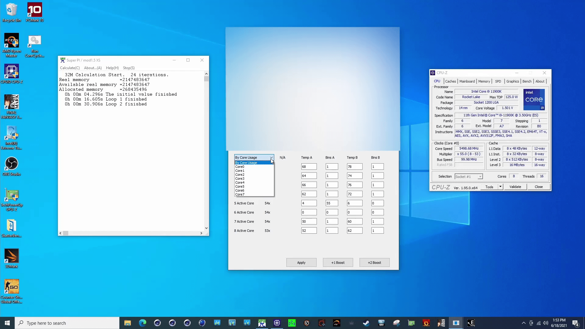
As you will see in a minute during the BIOS configuration, the +2-boost profile will push 2 cores to 5.5 GHz. Since not all of our cores are capable of 5.5 GHz, we need to use the special Rocket Lake feature Per Core Ratio Limit to ensure 5.5 GHz is only set for the cores that are capable of it.
I used a cool application called CoreCycler by Sp00n82 to test the overclocking capabilities of each core. Then I used that information to limit the maximum ratio for each core in the BIOS.
In addition to increasing the CPU ratio, we also increase the voltage for the highest CPU ratio using V/f point offset from 1.493V to 1.543V.
Upon entering the BIOS
- Go to the Extreme Tweaker menu
- Set AI Overclock Tuner to XMP I
- Set Intel Adaptive Boost Technology to Disabled
- Set Asus MultiCore Enhancement to Enabled – Remove All Limits
- Set CPU Core Ratio to AI Optimized
- Enter the Specific Core submenu
- Set Core0 to Core 1 Specific Ratio Limit to 55, 53, 54, 54, 55, 54, 54, 54.
- Leave the Specific Core submenu
- Enter the Thermal Velocity Boost submenu
- Set Overclocking TVB to +2Boost Profile.
- Leave the Thermal Velocity Boost submenu
- Enter the V/F Point Offset submenu
- Set V/F Point 8 Offset to 0.050
- Leave the V/F Point Offset submenu
- Enter the AI Features submenu
- Set Package Temperature Threshold to 85
- Set Regulate Temperature Threshold to Enabled
- Go to the Monitor menu
- Enter the Q-Fan Configuration submenu
- Enter the Chassis Fan Configuration submenu
- Set Chassis Fan Profile to Manual
- Set Chassis Fan Q-Fan Source to T_Sensor
- Set Chassis Fan Lower Temperature to 30
- Set Chassis Fan Middle Temperature to 35
- Set Chassis Fan Upper Temperature to 40
- Set Chassis Middle Duty Cycle to 60
- Enter the Chassis Fan Configuration submenu
Then save and exit the BIOS.
We re-ran the benchmarks and checked the performance increase compared to stock operation.
- SuperPI 4M: 4.78%
- Geekbench 5 (single): 9.05%
- Geekbench 5 (multi): 18.21%
- HWBOT X265 4K: 13.13%
- Cinebench R23 Single: 3.27%
- Cinebench R23 Multi: 8.12%
- V-Ray 5: 5.45%
- ROG Realbench V2.56: 9.46%
- 3DMark Night Raid: 6.27%
- CS:GO FPS Bench: 8.98%
- Final Fantasy XV: 10.77%

As you can see, the performance further improves.
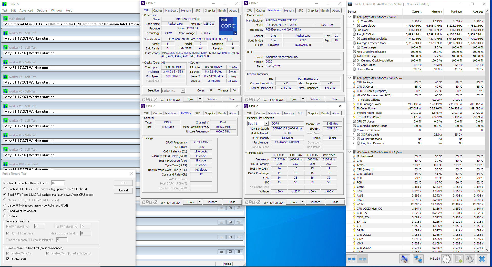
When running Prime 95 Small FFT with AVX enabled, the CPU operates stably at 4370 MHz with 1.121 volts. The average CPU temperature is 85 degrees centigrade, and the average water temperature is 37 degrees centigrade. The average CPU package power is 187.3 watts.
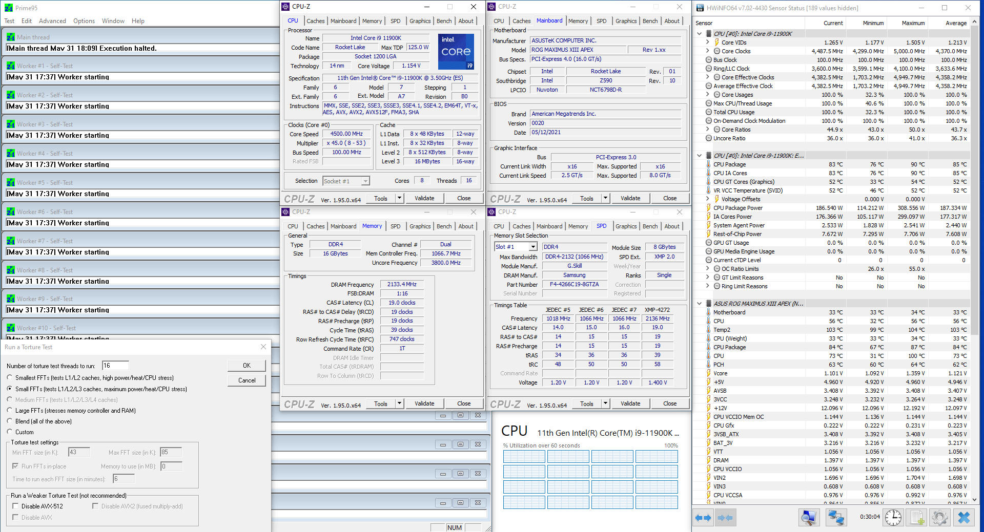
When running Prime 95 Small FFT with AVX disabled, the CPU operates stably at 4781 MHz with 1.195 volts. The average CPU temperature is 85 degrees centigrade, and the average water temperature is 37 degrees centigrade. The average CPU package power is 200.2 watts.
Now let us do some manual overclocking.
OC Strategy #4: Manual OC + OCTVB+2 + XMP + MCE
In our fourth and penultimate overclocking strategy we take matters into our own hands. Instead of relying on the ASUS AI, we configure the maximum CPU ratio by ourselves. However, we still rely on the +2 Boost Profile for our OCTVB configuration.
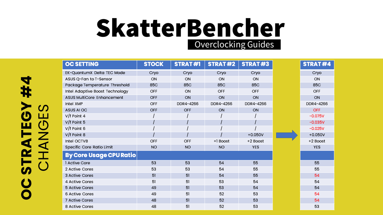
I particularly enjoy this configuration because on the surface it seems that the actual difference between Strategy 4 and Strategy 3 is close to nothing. In terms of CPU ratio configuration, we are a little less aggressive on frequency for 3 active cores and a little less aggressive on frequency for 6 and 7 active cores.
However, the big difference lies in the subtle tuning of the V/f Point Offsets.
As we noticed from the two previous Strategies, when pushing the CPU with Prime 95 the average frequency is around 4.78 GHz without AVX and 4.37 GHz with AVX-512. The limiting factor for this frequency is two-fold: (1) our configured CPU Package Temperature threshold of 85 degrees centigrade, and (2) the maximum power draw of the Delta TEC which is 200W.
As the system dynamically adjusts the CPU frequency to fit within these parameters, we find that the maximum real-world CPU voltage for Prime 95 Small FFTs without AVX is around 1.29V and for Prime 95 Small FFTs with AVX-512 is around 1.21V. These voltages are set according to the factory-fused V/f curve. To create extra frequency headroom, we can use the Advanced Voltage Offset feature to under-volt specific parts of the V/f Curve.
In our case, we adjust V/f Points 4, 5, 6, and 8. Under-volting the V/f Curve at Points 4, 5, and 6 allows us to achieve slightly higher frequency between 4.3GHz and 5.1GHz. Over-volting V/f Point 8 ensures stability for the highest CPU ratio.
Upon entering the BIOS
- Go to the Extreme Tweaker menu
- Set AI Overclock Tuner to XMP I
- Set Intel Adaptive Boost Technology to Disabled
- Set Asus MultiCore Enhancement to Enabled – Remove All Limits
- Set CPU Core Ratio to By Core Usage
- Set 1-Core to 8-Core Ratio Limit to 55, 55, 54, 54, 54, 54, 54, 53.
- Enter the Specific Core submenu
- Set Core0 to Core 1 Specific Ratio Limit to 55, 53, 54, 54, 55, 54, 54, 54.
- Leave the Specific Core submenu
- Enter the Thermal Velocity Boost submenu
- Set Overclocking TVB to +2Boost Profile.
- Leave the Thermal Velocity Boost submenu
- Enter the V/F Point Offset submenu
- Set Offset Mode Sign 4 to minus
- Set V/F Point 4 Offset to 0.075
- Set Offset Mode Sign 5 to minus
- Set V/F Point 5 Offset to 0.035
- Set Offset Mode Sign 6 to minus
- Set V/F Point 6 Offset to 0.025
- Set Offset Mode Sign 8 to plus
- Set V/F Point 8 Offset to 0.050
- Leave the V/F Point Offset submenu
- Enter the AI Features submenu
- Set Package Temperature Threshold to 85
- Set Regulate Temperature Threshold to Enabled
- Go to the Monitor menu
- Enter the Q-Fan Configuration submenu
- Enter the Chassis Fan Configuration submenu
- Set Chassis Fan Profile to Manual
- Set Chassis Fan Q-Fan Source to T_Sensor
- Set Chassis Fan Lower Temperature to 30
- Set Chassis Fan Middle Temperature to 35
- Set Chassis Fan Upper Temperature to 40
- Set Chassis Middle Duty Cycle to 60
- Enter the Chassis Fan Configuration submenu
Then save and exit the BIOS.
We re-ran the benchmarks and checked the performance increase compared to stock operation.
- SuperPI 4M: 4.89%
- Geekbench 5 (single): 9.45%
- Geekbench 5 (multi): 19.40%
- HWBOT X265 4K: 14.25%
- Cinebench R23 Single: 3.51%
- Cinebench R23 Multi: 8.53%
- V-Ray 5: 6.36%
- ROG Realbench V2.56: 9.55%
- 3DMark Night Raid: 6.62%
- CS:GO FPS Bench: 9.91%
- Final Fantasy XV: 11.27%
We achieve the highest performance across all benchmarks so far. Both the single-threaded performance gain of up to 9% and the CPU multi-threaded performance gain of up to 19% are quite impressive, as is the increase of up to 11% in our game benchmarks.
Using the negative V/f Point Offset feature gave us about 100 MHz extra in Prime 95.
When running Prime 95 Small FFT with AVX enabled, the CPU operates stably at 4493 MHz with 1.111 volts. The average CPU temperature is 85 degrees centigrade, and the average water temperature is 37 degrees centigrade. The average CPU package power is 187.6 watts.
When running Prime 95 Small FFT with AVX disabled, the CPU operates stably at 4862 MHz with 1.194 volts. The average CPU temperature is 85 degrees centigrade, and the average water temperature is 37 degrees centigrade. The average CPU package power is 200.8 watts.
OC Strategy #5: Manual OC + OCTVB + XMP + MCE
In our final overclocking strategy, we make a couple of important changes to our configuration compared to the fourth overclocking strategy.
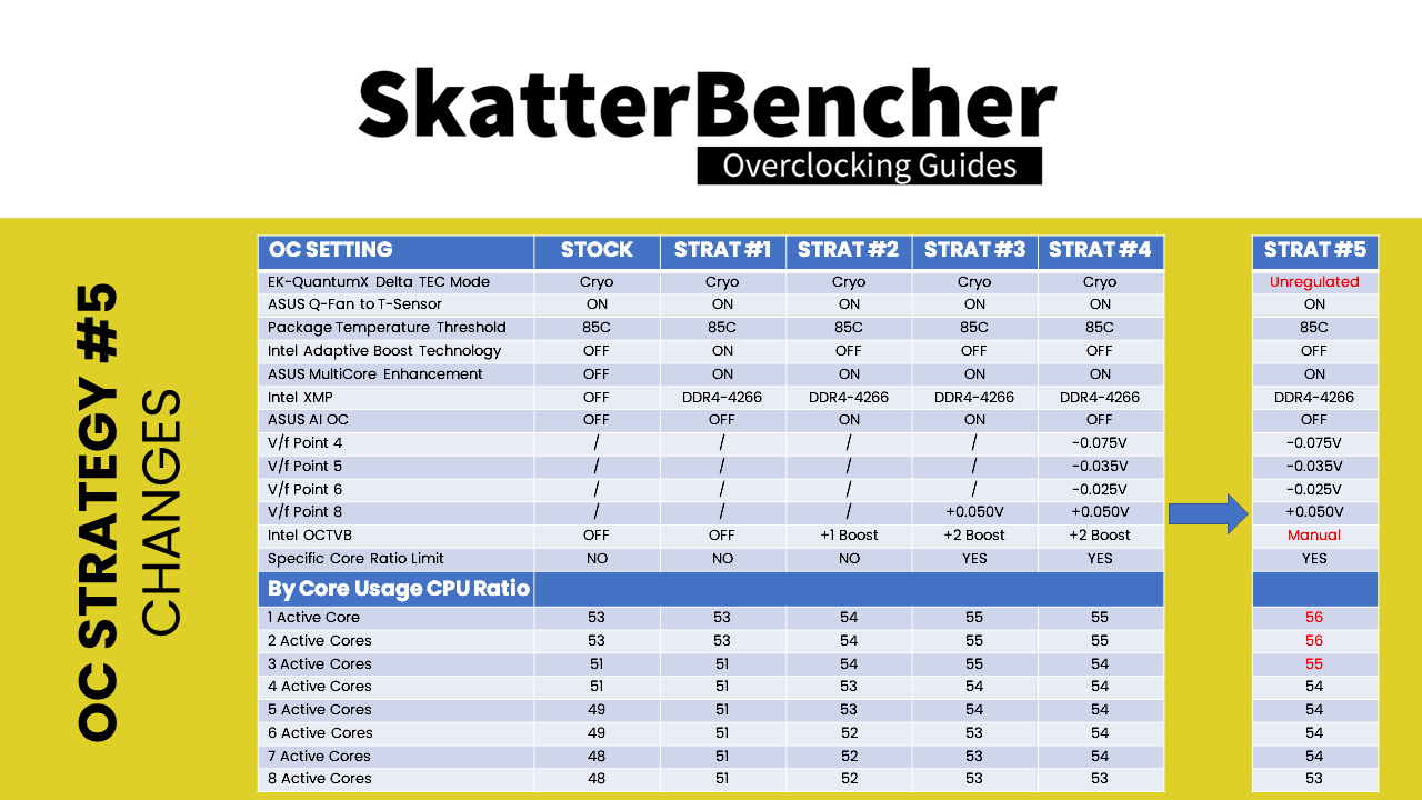


- First, we push the maximum CPU frequency for 1 active core up to 3 active cores up by 1 ratio. This will increase the performance in lightly threaded workloads as the CPU can now boost up to 5.6 GHz for up to 2 cores. We keep the manual V/f Point Offset configuration.
- Second, we manually configure the OCTVB. The main focus is to ensure that the peak frequencies are only set when the CPU temperature is low enough.
- Third, we change the Cryo Cooler setting from Cryo mode to Unregulated mode.
We talked about the difference between the Cryo and Unregulated mode in SkatterBencher episode 19. In case you forgot or, god forbid, did not watch that video, let me reiterate:
In Cryo mode, the Peltier element inside our Delta TEC water block is only switched on when required and is switched off when not required. This greatly reduces the overall power consumed as the TEC is not running at full power all the time. The Intel software regulates the cooler temperature by assessing the humidity in the room as well as the CPU temperature. Based on this input, the software ensures that maximum cooling is provided at any time while ensuring the temperature does not drop below the dew point and cause condensation issues. This mode is indicated by a green icon in the desktop tray and a green LED on the TEC controller.
In Unregulated mode, the Delta TEC cools well below ambient temperature with less protection from condensation. In this mode there will be condensation risk on the heatsink surfaces and surroundings due to the low temperature. It can cause system damage. This mode is indicated by a white icon in the desktop tray and a purple LED on the TEC controller.
Upon entering the BIOS
- Go to the Extreme Tweaker menu
- Set AI Overclock Tuner to XMP I
- Set Intel Adaptive Boost Technology to Disabled
- Set Asus MultiCore Enhancement to Enabled – Remove All Limits
- Set CPU Core Ratio to By Core Usage
- Set 1-Core to 8-Core Ratio Limit to 56, 56, 55, 54, 54, 54, 54, 53.
- Enter the Specific Core submenu
- Set Core0 to Core 1 Specific Ratio Limit to 56, 53, 55, 55, 56, 56, 54, 54.
- Leave the Specific Core submenu
- Enter the Thermal Velocity Boost submenu
- Set Overclocking TVB to Enabled
- Set 1-Core to 8-Core Active to Enabled
- For 1-Core to 8-Core Active, set Temperature A to 25, 20, 60, 64, 62, 60, 56, 52.
- For 1-Core to 8-Core Active, set Negative Ratio Offset A to User Specify
- For 1-Core to 8-Core Active, set Ratio Offset to 1
- For 1-Core to 8-Core Active, set Temperature A to 55, 45, 70, 74, 72, 70, 66, 62.
- For 1-Core to 8-Core Active, set Negative Ratio Offset B to User Specify
- For 1-Core to 8-Core Active, set Ratio Offset to 1
- Leave the Thermal Velocity Boost submenu
- Enter the V/F Point Offset submenu
- Set Offset Mode Sign 4 to minus
- Set V/F Point 4 Offset to 0.075
- Set Offset Mode Sign 5 to minus
- Set V/F Point 5 Offset to 0.035
- Set Offset Mode Sign 6 to minus
- Set V/F Point 6 Offset to 0.025
- Set Offset Mode Sign 8 to plus
- Set V/F Point 8 Offset to 0.050
- Leave the V/F Point Offset submenu
- Enter the AI Features submenu
- Set Package Temperature Threshold to 85
- Set Regulate Temperature Threshold to Enabled
- Go to the Monitor menu
- Enter the Q-Fan Configuration submenu
- Enter the Chassis Fan Configuration submenu
- Set Chassis Fan Profile to Manual
- Set Chassis Fan Q-Fan Source to T_Sensor
- Set Chassis Fan Lower Temperature to 30
- Set Chassis Fan Middle Temperature to 35
- Set Chassis Fan Upper Temperature to 40
- Set Chassis Middle Duty Cycle to 60
- Enter the Chassis Fan Configuration submenu
Then save and exit the BIOS.
We re-ran the benchmarks and checked the performance increase compared to stock operation.
- SuperPI 4M: 6.25%
- Geekbench 5 (single): 10.76%
- Geekbench 5 (multi): 20.54%
- HWBOT X265 4K: 14.28%
- Cinebench R23 Single: 4.06%
- Cinebench R23 Multi: 8.60%
- V-Ray 5: 7.58%
- ROG Realbench V2.56: 9.64%
- 3DMark Night Raid: 6.72%
- CS:GO FPS Bench: 10.51%
- Final Fantasy XV: 11.37%

As we had hoped for, we achieve the highest performance in all benchmarks with our latest overclocking strategy.
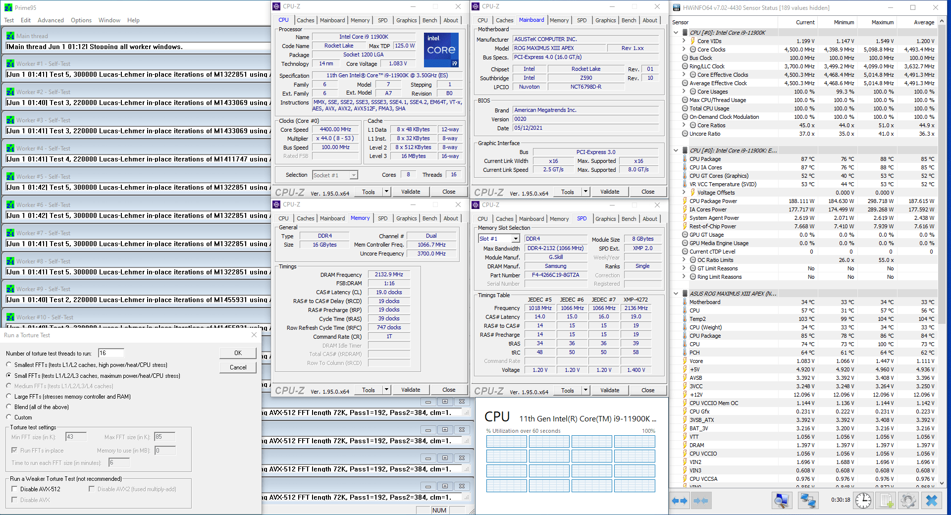
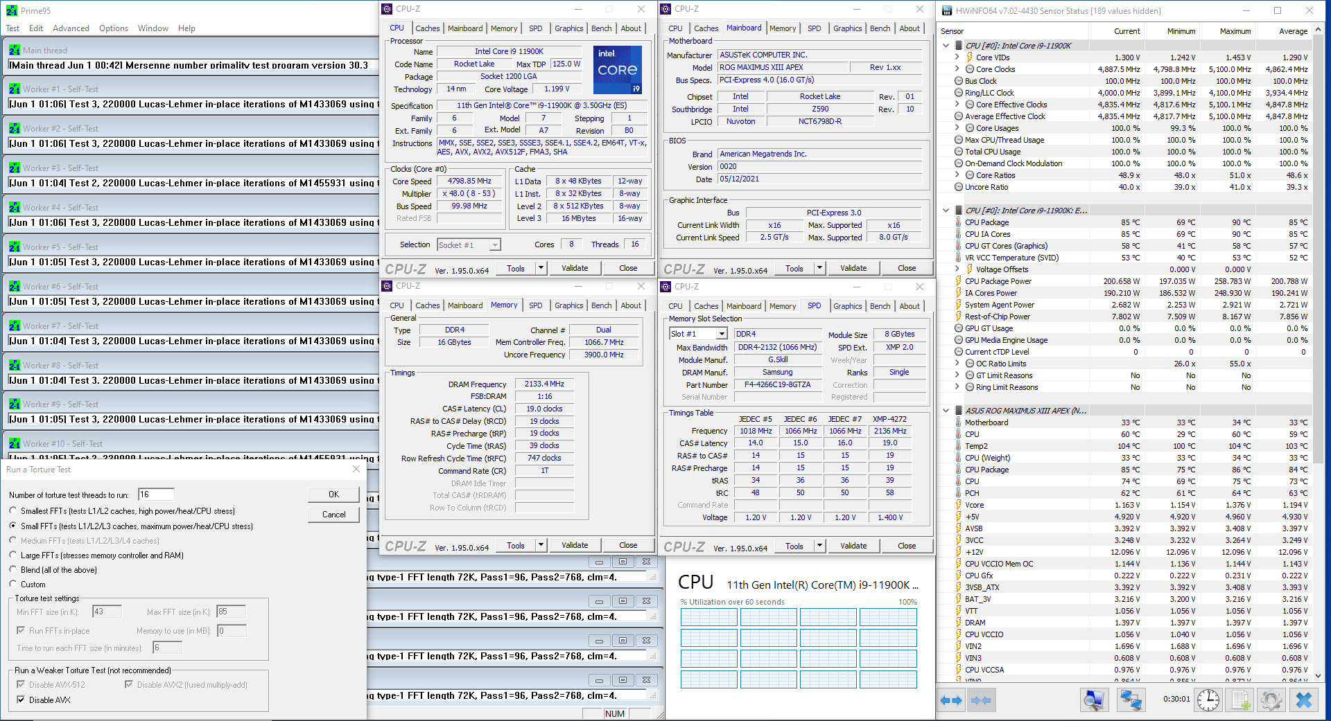
When running Prime 95 Small FFT with AVX enabled, the CPU operates stably at 4523 MHz with 1.113 volts. The average CPU temperature is 85 degrees centigrade, and the average water temperature is 37 degrees centigrade. The average CPU package power is 190.1 watts.
When running Prime 95 Small FFT with AVX disabled, the CPU operates stably at 4831 MHz with 1.191 volts. The average CPU temperature is 85 degrees centigrade, and the average water temperature is 37 degrees centigrade. The average CPU package power is 200.5 watts.
Core i9-11900K Cryo Conclusion
Alright, let us wrap this up.
Overall, I am pretty satisfied with the final overclocked configuration. It was nice to finally get around to use all the available Intel overclocking knobs and put them to good use. I found that most available knobs can be effective and useful.
Comparing the final overclocking strategy with the default configuration, in an ideal scenario we get up to 300 MHz higher frequency when up to 2 cores are active, and up to 500MHz higher frequency when all 8 cores are active.
In Prime 95 with AVX-512 that translates into an effective frequency increase from 3.8 GHz to 4.5 GHz and in Prime 95 without AVX into an effective frequency increase from 4.3 GHz to 4.8 GHz. The benchmark performance increased up to 11% for single threaded workloads, up to 21% for multi-threaded workloads, and up to 11% in gaming workloads. Not bad at all!
The Per Core Ratio Limit feature allowed me to restrict the weaker cores from boosting to frequencies they cannot run stably. This is a big improvement of Rocket Lake compared to Comet Lake, especially at the higher frequency range of 5.6GHz.
Tuning the voltages with V/f Point Offset gave me an additional 100MHz in multi-threaded heavy workloads when temperature and power is constraint by an already maxed out system. I was happy when I saw those results and finally can appreciate the power of V/f Point Offset compared to other methods of adjusting the CPU voltage.
OCTVB did not change that much from Comet Lake, other than the ability to configure down bin B. While I was able to idle in the operating system at 5.7 GHz, I was not able to dial this in in a stable overclock configuration. This is quite a bit lower than the 6 GHz we saw with the Comet Lake 10900K in SkatterBencher episode 19.
The maximum frequency of 5.6 GHz is primarily limited by the Rocket Lake architecture not scaling that well with temperature. However, this is not new information as the maximum CPU frequency achieved with liquid helium was 7.3 GHz for Rocket Lake and 7.7 GHz for Comet Lake. So, yea, using strong ambient cooling solutions Rocket Lake can match Comet Lake in frequency, but when it comes to sub-ambient solutions Comet Lake seems to scale better.
All things considered; this was still loads of fun. It took me about two weeks to dial in the final overclock settings and three more weeks to finalize the video. While the frequency in the end is not that satisfying, it is really cool to make use of all the different overclocking knobs and features to push the system to its max.
Thanks for reading! As per usual if you have any questions or comments, feel free to drop them in the comment section below. ‘Till the next time.
Adrian
Hi there Pieter. Appreciate your great work … a question , did you touch the Load-Line Calibration? Or I should just leave it to auto?
Pieter
Thanks! It’s been a while so I don’t quite recall. But as a general rule of thumb I always include all settings in my BIOS settings. So if I don’t mention it in the settings list, I didn’t adjust it for the OC Strategy.
Adrian
Great. Thanks for your quick response. 👍
Adrian
I forgot to ask for how long I should run Prime 95 to make sure the OC is stable?
Adrian
I run a bit into a problem.
I OC’d strategy 5 everything runs smooth and nicely. I run Prime 95 on ‘Blend all …’ with AVX enabled for 30 miunutes and passed it was running on ~4500Mhz-4800Mhz on average temps of 85 and max was 97. After I run a small FFT with AVX disabled for 1 hour and I got an average temp of 81 and max of 87. No errors running very smooth.
Now the issue comes when I tried to run a test in Cinebech I’ve got an instant crash. What should I do in this matter? Should I try to run the AI spec? or leave it like it is because Prime 95 said is safe….?
My specs are :
Operating System
Windows 11 Pro 64-bit
CPU
Intel Core i9 11900K @ 3.50GHz
Rocket Lake 14nm Technology
RAM
64.0GB Dual-Channel DDR4
Motherboard
ASUS ROG STRIX Z590-E GAMING WIFI (LGA1200)
Graphics
DELL U2518D (2560×1440@59Hz)
XB271HU (2560×1440@165Hz)
4095MB NVIDIA GeForce RTX 3080 Ti (ASUStek Computer Inc)
Storage
238GB SAMSUNG SSD 830 Series
931GB Seagate FireCuda 510 SSD
223GB Force MP500
Case
Corsair 7000D AIRFLOW
x6 Corsair RS140 ARGB 140mm PWM Fans(magnetic levitation)
x2 Corsair RS120 ARGB 140mm PWM Fans(magnetic levitation)
Water pump cooling system
EK Water Blocks EK-Quantum Kinetic TBE 160 DDC PWM D-RGB Pump, and CPU body
Can’t remember the radiator Brand and model …. but is a high end one.
SkatterBencher #52: Intel Core i9-13900K P-core Overclocked to 6500MHz - SkatterBencher
[…] a new and improved overclocking experience on a desktop. I extensively covered this technology in SkatterBencher #19, so I won’t go into detail in this article. But for those who don’t know this […]
martin von reitzel
Nice that you spend so much time on it, I would like to know if you have to set IA AC/DC loadlines, when I drive with all cores locked to the same speed, I get 16XXX chinbench 23 at only 5GHZ 1.4v and avx2 set to 0
can IA AC/DC loadlines help me to run low vcore?
Pieter
I didn’t touch the AC DC loadline values in this guide.
By lowering the AC value, you can reduce the effective CPU core voltage. The AC LL value essentially positively offsets the CPU VID (according the CPU factory-fused voltage-frequency curve) to ensure that by the time voltage reaches the CPU core die (from the CPU VRM, requested by the CPU using the VID) is still at minimum that factory-fused voltage point. If you reduce the AC LL value, you can effectively undervolt the CPU.
SkatterBencher #51: Intel Core i5-13600K Overclocked to 6200MHz - SkatterBencher
[…] briefly covered this feature in the Alder Lake launch video and SkatterBencher #25 with the Core […]
SkatterBencher #28: Intel UHD Graphics 750 Overclocked to 1750 MHz | SkatterBencher
[…] also overclock our 8 Rocket Lake CPU cores using the same settings we used in SkatterBencher #25 OC Strategy #4. So, we manually tune the CPU ratios and use ASUS’ OCTVB +2 Boost Profile to get frequencies up […]
Heinz Drewing
As usual, a superb overclocking article. I’m running the Apex XIII with the 11900K. Asus AI gives me an overclock of 54%. The AI Prediction shows SP 93 and Cooler 188 pts. I’m very happy with the “analysis”, given that cooling is a Noctua NH D15.
My concern and question really is VID of ca. 1.45V full time. I’m extremely happy but is it safe? Max temps running various benches (excluding Prime 95) never exceed 87 degrees. Unable to find useful info on Intels data sheets.
Regards and Cheers
Heinz Drewing
Pieter
Hi Heinz, thanks for the kind words!
Regarding the VID of 1.45V: if you’re using ASUS AI OC to get your overclock, it will be using Adaptive Voltage Mode. That means the voltage will change dynamically and on the fly according to the CPU ratio. The adaptive voltage setting of 1.45V will only be applied when the highest ratio is active which is usually when only few cores are active and it’s a non-AVX workload. In those scenarios 1.45V is no problem.
Just remember that the 1.45V is not applied to all cores all the time 🙂
ElmorLabs EFC Easy Fan Controller | SkatterBencher
[…] If you have been following this website for a while, you will know that we have looked at Intel Cryo Cooling a couple of times now. We used Intel Cryo Cooling to get a 6 GHz Comet Lake system and a 5.6 GHz Rocket Lake system. […]