SkatterBencher #19: Intel Core i9-10900K Overclocked to 6000 MHz

We overclock the Intel Core i9-10900K processor up to 6000 MHz with the ASUS ROG Maximus XII Apex motherboard and Intel Cryo cooling.
Introduction
Today we’re overclocking the Core i9-10900K processor to 6 GHz using the Intel Cryo Cooling technology integrated in the EK-QuantumX Delta TEC water block.
This overclocking guide will be a slightly different format compared to the usual Skatterbencher videos as we’ll talk a bit more in detail about the various Intel technologies we use to get our best overclocking result. So, yea, it’s going to be a long video.
Here’s how we’ll go about it.
- First, we’ll have a closer look at what is Intel Cryo Cooling Technology.
- Then, we will have a look at the BIOS configuration to get to 6 GHz.
- Then, I will go over each of the BIOS settings to explain why I’m using that specific setting.
- After that, we’ll have a look at the performance gains from overclocking with the Intel Cryo Cooling Technology versus a regular high-end custom loop water cooling setup.
And we’ll finish it off with some concluding thoughts.
If you’re looking for a simpler guide to overclocking the Core i9-10900K, feel free to check out SkatterBencher episode #10.
However, before we dive in the BIOS, let’s have a look at the hardware components used in this guide and what Intel Cryo Cooling Technology is all about
Intel Core i9-10900K Cryo: Platform Overview
Along with the Intel Core i9-10900K processor, in this guide we will be using
- The ASUS ROG Maximus XII APEX motherboard,
- An ASUS ROG STRIX RTX 2080 TI graphics card,
- a pair of G.SKILL Trident Z DDR4-4266 memory sticks,
- a Seasonic Prime 850W Platinum power supply,
- the Elmorlabs P80DB2 LPC Debug Card,
- and of course EK-QuantumX water cooling.
All this is mounted on top of our favorite Open Benchtable.
The cost of the components should be around $4,630
- CPU: $530
- Cooling: $360 + $400
- Motherboard: $660
- VGA: $2100
- Memory: $150
- Power Supply: $200
- Debug card: $30
- Benchtable: $200
Intel Cryo Cooling Technology
https://www.intel.com/content/www/us/en/products/docs/processors/core/cryo-cooling.html
Intel Cryo Cooling Technology is touted as an intelligent sub-ambient cooling product that offers a new and improved overclocking experience on desktop.
It takes advantage of the Intel Thermal Velocity Boost feature which aims to improve system performance by increasing the CPU frequency based on the CPU temperature. The Thermal Velocity Boost is a different from the regular Turbo Boost as Turbo Boost looks primarily at the available power budget.
The Cryo Cooling technology is built around the thermoelectric effect. Simply put, the thermoelectric effect is the conversion of differences in temperature to an electric voltage and vice versa. In the PC enthusiast space it is best known as Peltier cooling.
https://ii-vi.com/how_do_thermoelectric_coolers_tec_work/
The Peltier effect creates a temperature difference by transferring heat between two electrical junctions. A voltage is applied across joined conductors to create an electric current. When the current flows through the junctions of the two conductors, heat is removed at one junction and cooling occurs. Heat is deposited at the other junction.
Simply put: more voltage makes one side go “haaa” and the other side go “brrrr”.
The main advantage of Peltier cooling for PC enthusiasts is that it allows you to get sub-ambient temperatures. And as we all know, lower temperatures means higher overclocks.
Peltier cooling has been around for a long time in the PC enthusiast space.
- 1997 https://www.anandtech.com/show/27/2
- 1999 Swiftech MC Cooler MC1000 https://www.anandtech.com/show/353
- 1999 Swiftech MC370 https://www.anandtech.com/show/426/
- 2003 Thermaltake SubZero4G TEC http://oyvind.servehttp.com/thermaltake_subzero4g_tec.htm
- 2004 ActiveCool AC4G Thermoelectric cooler https://silentpcreview.com/review-activecool-ac4g-thermoelectric-cooler/
- 2006 CoolIt Systems Freezone Peltier https://pcper.com/2006/11/coolit-systems-freezone-peltier-cpu-cooler-review/
- 2007 CoolIT Eliminator https://www.legitreviews.com/the-coolit-eliminator-cpu-cooler-review_473
- 2007 ChillTec TEC Cpu Cooler https://www.legitreviews.com/the-chilltec-thermoelectric-cpu-cooler-review_491
- 2009 Cooler Master V10 https://www.overclockersclub.com/reviews/cm_v10/
- 2014 V3 Voltair https://www.tweaktown.com/reviews/6487/v3-voltair-high-performance-thermoelectric-cpu-cooler-review/index.html
- 2016 Phononic HEX 2.0 TEC https://www.anandtech.com/show/10695/the-phononic-hex-2-0-tec-cpu-cooler-review
I don’t want to go too deep in the what’s and why’s of TEC cooling, but suffice to say it’s a technology that’s been around for over two decades and hasn’t really found any footing in the mainstream market. That’s because while the technology offers the clear advantage of superior cooling performance, there are also key disadvantages.
First, condensation. A Peltier cooler can produce a temperature difference of up to 70c between the hot and cold side. So, the cold side will be operating at a lower temperature than ambient. This will create condensation … which doesn’t mix well with electronics.
Second, efficiency. Peltier cooling consumes disproportionally high amounts of electrical energy for the heat it dissipates.
Third, cooling. In order to maximize the benefit of the Peltier you need to cool the hot side sufficiently. High performance Peltier units like the one included with the EK-QuantumX Delta are rated up to 200W which is significantly higher than a modern mainstream high-performance CPU like the 10900K which is rated up to 125W.
Lastly, control. Most Peltier coolers out there provide the user with no control over the cooling. So it’s either on or off, but no in between.
So What Makes Intel Cryo Different?
I hear you asking already: if this has been tried, tested, and found not viable for over two decades … why is the Intel Cryo Cooling Technology so interesting?
Well, a couple of things actually.
First, the Intel Cryo Cooling Technology offers a software solution to control the Peltier temperature. In Cryo mode, the TEC cooling is only switched on when required and is switched off when not required. This greatly reduces the overall power consumed as the TEC is not running at full power all the time.
Second, the Intel controller also measures the humidity in the room. Based on this input, the controller can adjust the TEC temperature to always be above the dew point. This helps to avoid any condensation issues.
Thirdly, it maximizes the impact of the Intel Thermal Velocity Boost feature by ensuring best-case operating temperatures. Using Thermal Velocity Boost also allows us opportunistically benefit from the added frequency range as the frequency adjusts based on when we really need it.
All things combined, the Intel Cryo Cooling Technology is arguably be the most advanced and well-rounded implementation of thermoelectric cooling for enthusiasts to date.
At the moment of recording the Intel Cryo Cooling Technology is compatible with all 10th generation -K and -KF desktop processors from the i5-10600KF to the i9-10900K.
So, without further ado, let’s get our overclock on.
The 6GHz Overclock
Okay, so before I show you the settings I use to achieve 6 GHz, a word of warning. Do not try these settings at home, unless you have this cooling solution and unless you know what you’re doing. This is definitely not a beginner’s guide and there’s an increased risk of damaging your components. So, be careful!
BIOS Configuration
Upon entering the bios:
- Enter the Extreme Tweaker menu
- Set Ai Overclock Tuner to XMP II
- Set ASUS MultiCore Enhancement to Enabled – Remove All Limits
- Set CPU Core Ratio to By Core Usage
- Enter the By Core Usage submenu
- Set Turbo Ratio Limit 0 to 60
- Set Turbo Ratio Cores 0 to 4
- Set Turbo Ratio Limit 1 to 54
- Set Turbo Ratio Cores 1 to 6
- Set Turbo Ratio Limit 2 to 52
- Set Turbo Ratio Cores 2 to 10
- Exit the By Core Usage submenu
- Enter the Thermal Velocity Boost submenu
- Set Overclocking TVB to Enabled
- Set 1-Core Active to 10-Core Active to Enabled
- Set Negative Ratio Offset A for 1-Core Active to 10-Core Active to User Specify
- Then for 1-Core Active to 10-Core Active set Temperature A, Negative Ratio Offset A, and Temperature B for additional -1x Ratio to the following:
- 1-Core: 10, 3, 55
- 2-Core: 10, 3, 51
- 3-Core: 10, 4, 47
- 4-Core: 10, 4, 43
- 5-Core: 58, 1, 68
- 6-Core: 54, 1, 64
- 7-Core: 62, 1, 72
- 8-Core: 58, 1, 68
- 9-Core: 54, 1, 64
- 10-Core: 50, 1, 60
- Exit the Thermal Velocity Boost submenu
- Enter the Tweaker’s Paradise submenu
- Set Internal PLL Voltage to 0.9
- Set Ring PLL Voltage to 0.9
- Set PLL Bandwidth to Level 1
- Set Eventual PLL Termination Voltage to 1.05
- Exit the Tweaker’s Paradise submenu
- Enter the AI Features submenu
- Set Package Temperature Threshold to 85
- Set Regulate Frequency by above Threshold to Enabled
- Exit the AI Features submenu
- Set CPU Core/Cache Voltage to Adaptive Mode
- Set Additional Turbo Mode CPU Core Voltage to 1.550
- Go to the Advanced Menu
- Enter the CPU Configuration submenu
- Enter the CPU – Power Management Control submenu
- Ensure CPU C-states is set to enabled
- Go to the Monitor menu
- Enter the Q-Fan Configuration submenu
- Enter the Chassis Fan Configuration submenu
- Set Chassis Fan Q-Fan Control to Auto
- Set Chassis Fan Q-Fan Source to T_Sensor
- Set Chassis Fan 2 Profile to Manual
- Set the upper temperature to 50
- Set the max duty cycle to 100%
- Set the middle temperature to 30
- Set the middle duty cycle to 60
- Set the lower temperature to 25
- Set the min duty cycle to 20%
- Enter the boot menu
- Set Wait for ‘F1’ If Error to Disabled
Save and exit the bios.
When in the Operating System, make sure to set the Intel Cryo Cooling to Unregulated Mode.
Now, wait until the CPU is sufficiently cooled down and you’ll see the CPU running at 6 GHz.
Now, let’s rewind and let’s explain the BIOS settings in more detail.
BIOS Configuration Explained
XMP – Extreme Memory Profile
Intel Extreme Memory Profile, or XMP, is a technology that lets you automatically overclock the system memory to improve system performance.
XMP is an extension to the standard JEDEC specification that allows a memory vendor to program different settings onto the memory stick. The settings include the memory frequency, the memory timings and the memory voltage.
The Intel XMP standard uses this extension for overclocking purposes and adds a couple of features to the memory standard:
- Multiple SPD profiles – Allows for a number of different memory profiles which can be selected depending on the usage; for example for a special low-latency custom profile for gaming.
- Memory vendor specific SPD fields – This gives memory module suppliers the ability to set a number of their own profiles based on the module capabilities.
- Easy Over-clocking (Novice) – Provides users with a number of predefined overclocked profiles that have been determined to be stable. This allows users to selected those predefined profiles instead of adjusting individual parameters in BIOS.
- Advanced Overclocking (Intermediate/Expert Users) – Allows more advanced users to change specific SPD parameters in the BIOS and save those profiles.
- Fail-safe default boot – Allows the ability to restore to one of the usual default JEDEC settings after a bad settings
There are two types of XMP certification:
- XMP ready: the module was programmed with an uncertain, but stable, profile
- XMP Certified: the module was programmed with settings that have passed supplier tests for the CPU and motherboard.
You can find the list of XMP Certified products on Intel’s website.
If you want to know which XMP profiles your memory supports, there are several ways to do it.
First, if your memory is rated above DDR4-3200, it almost definitely has an XMP profile. That’s because the JEDEC standard only goes up to DDR4-3200.
Second, you can look in your BIOS and find the option to enable XMP. Most, if not all, motherboards support XMP and even allow you to check the specific configuration in BIOS.
Third, you can use CPU-Z and check the SPD tab. Here you will find the basic XMP profile settings in the Timings Table section.
I almost always run XMP on my systems because it’s an incredibly easy and safe way to improve system performance. Do note that some motherboards may adjust CPU memory controller voltages to support very high frequency memory.
In this case, our memory kit is rated DDR4-4266 with CAS latency 19 and a voltage of 1.40V. Simply enabling XMP in the BIOS will configure the system.
Intel Turbo Boost Technology
If we have a quick look at the Intel Core i9-10900K product specifications, we can find three boost technologies listed:
- Intel Thermal Velocity Boost
- Intel Turbo Boost Max Technology 3.0
- Intel Turbo Boost Technology 2.0
Let’s have a closer look at those last two.
Geyserville
Intel has a long history of trying to give customers additional out of the box performance. In fact, the history of Turbo Boost goes way waaay back to February 1999.
During the Spring’99 Intel Developer Forum Intel announced the Geyserville technology. Geyserville would switch the operating frequency and voltage of a notebook processor depending on whether it’s connected to AC power or battery powered. When using AC power, the frequency of the Mobile Pentium III 400 processor increases to 500 MHz.
Later that same year, during the Computex tradeshow, Intel demoed two notebook prototypes with the technology enabled. Geyserville would eventually make it to market rebranded as SpeedStep.
Turbo Boost
About a decade and many iterations of dynamic frequency technologies later, including Enhanced SpeedStep and various forms of Dynamic Acceleration Technology, in 2008 Intel introduced Turbo Boost 1.0 along with the Intel Core Microarchitecture codenamed Nehalem.
Intel Turbo Boost Technology automatically allows the processor cores to run faster than the base operating frequency if the processor is operating below rated power, temperature, and current specification limits. The ultimate advantage is opportunistic performance benefits in both multi-threaded and single-threaded workloads.
Turbo Boost 2.0
Three years later, Intel introduced a second version of Turbo Boost called. Ehr. Turbo Boost 2.0. While the general principles are the same, there are some key differences between Turbo Boost 1.0 and Turbo Boost 2.0.
- First, Turbo Boost 2.0 increased the amount of turbo bins over base frequency
- Second, Turbo Boost 2.0 factors into account not only the CPU cores but also the other parts of the CPU die. For example, the integrated graphics can boost to higher frequency in gaming workloads where the GPU performance is more important than the CPU performance.
- But most importantly, Turbo Boost 2.0 expands the power budget to well above the TDP rating.
This last point is crucial to understanding how Turbo Boost works. Take note: the processor can safely operate above TDP for short periods of time when there is sufficient headroom.
Now, I urge you to pay attention to what’s coming as it will play an important role when setting up our system.
The headroom expands when the processor has been at lower power for a while or if you have a superior cooling solution. The headroom is reduced when the system has been running at high power or if you have an inferior cooling solution.
So, what are the limits then?
The turbo boost algorithm works according a proprietary EWMA formula. This stands for Exponentially Weighted Moving Average. The exact formula is not known, but we can do a simple test to demonstrate the behavior.
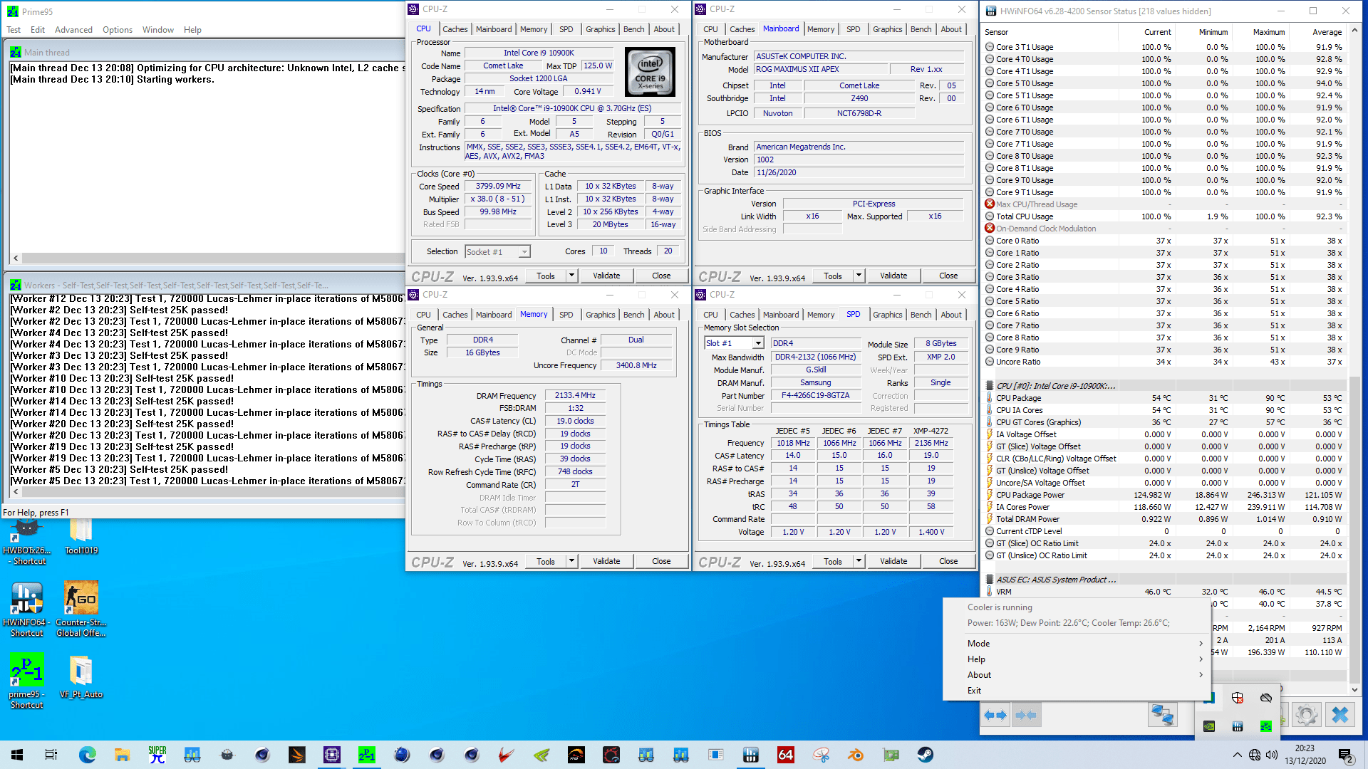
To demonstrate how Turbo Boost 2.0 works, I set the BIOS to enforce all default turbo boost limits.
Then I use Prime 95 to track the CPU package power.
When we run Prime 95 with AVX, you can see that the turbo is enabled for about 38 seconds. The power consumption reaches 235W and then drops sharply to 125W.
If we run Prime 95 without AVX, the turbo is enabled for about 45 seconds. That’s because the power consumption is only 210W.
The power budget at the beginning of each test is the same. However, since our non-AVX workload is less demanding, the power budget is consumed at a rate that’s much lower than our AVX workload. So, we can turbo for longer.
When we run an even less demanding workload with 8 threads compared to the default 20 threads, we can see that the turbo boost duration is much longer. The turbo boost is maintained for well over 1 minute. That’s because the power consumption only reaches about 160W.
If we add an additional voltage offset of 0.1V on top of our most demanding workload of Prime 95 with AVX and all 20 threads enabled, we can see a big impact on the turbo boost. Instead of 38 seconds, we only get 29 seconds of turbo time. That’s because more voltage means more power. In our case, the power increases to almost 250W.
Lastly, just for comparison, here’s what the chart looks like with unlocked power limits. The CPU package power reaches over 275W sustained. While this will deliver amazing performance, it will also need a strong cooling solution.
I also tracked a bunch of other metrics and put them in a table. You can see that depending on your workload and the Turbo Boost configuration, you can see a wide range of frequencies, voltages and power consumption figures.
So what’s the main takeaway from all this? Well:
- The more power we need for our workload, the fewer time the CPU will exceed the TDP
- Eventually, the system will always return to PL1
Turbo Boost Max Technology 3.0
In 2016, Intel introduced the Turbo Boost Max Technology 3.0. While carrying the name, Turbo Boost Max 3.0 is not really an iteration on Turbo Boost 2.0.
Turbo Boost Max Technology 3.0 aims to exploit the natural variance in CPU core quality observed in multi-core CPUs. As you may know, there is certain variance in overclocking capabilities between CPUs. Well, there is also a certain variance in quality between the cores in a CPU.
With Turbo Boost Max 3.0, Intel has a way of identifying the best cores in your CPU and calls those the “favored cores”. The favored cores are important for two reasons.
- Intel allows for additional overclocking of the favored cores. On the Comet Lake 10900K, two out of the ten cores will boost to 5.3 GHz while the others are limited to 5.1 GHz
- The operating system will automatically assign the most demanding workloads to these favored cores ensuring a potential higher performance.
On Broadwell-E, Turbo Boost Max 3.0 was available for 1 core. On Skylake-X this feature expanded to 2 cores. The latest iteration of Turbo Boost Max 3.0 Technology allows boosting of up to 4 cores on certain architectures.
On Comet Lake and the 10900K, the best two cores will boost to the maximum frequency while the other cores will boost to 100 MHz lower than the max frequency.
The performance benefit of ITBMT 3.0 is most visible in low thread count workloads. Highly threaded workloads do not benefit from ITBMT 3.0.
In some motherboard BIOSes you can find out which of your CPU’s cores are the favored cores.
Now that we know how Turbo Boost works, we can understand our BIOS configuration. We unlock the power limits because we don’t want any constraints when overclocking.
We can also make some predictions.
- It’s very likely that two out of the 10 cores have higher overclocking capabilities than the others
- Unlocking the power limits may cause severe thermal issues in very demanding workloads
These two points will be addressed at a later stage in our configuration.
By Core Usage
There are two ways to manually configure the CPU ratio: Sync all cores and By Core Usage
Sync All Cores sets 1 ratio that is applied to all cores. This is very much the traditional way of overclocking.
Of course, back in the day where we only had 1, 2, 3 or four cores, the quality difference between the cores was relatively small. So there was not that much benefit to max out each core independently.
Nowadays, even mainstream CPUs have up to 16 cores. Meaning that the quality difference between the cores can vary greatly. In addition, the heat produced by 16 cores at full load will be much higher than the heat produced by a couple of cores at light load. So, if you tune your system for the worst-case scenario, you’ll miss out on some performance in the most common scenarios.
By Core Usage allows us to configure the overclock for different scenarios ranging from 1 active core to all 10 active cores. This enables us to run some cores significantly faster than others when the conditions are right.
Note that By Core Usage is not the same as configuring each core specifically. When using By Core Usage, we determine an overclock according to the actual usage. For example, if a workload is using 4 cores then the CPU will determine by itself which cores should execute this workload and will apply our set frequency to those cores.
In our case, we configure the CPU to set 60x ratio for up to 4 active cores, 54x for up to 6 active cores, and 52x for up to all cores active.
As you can see, we are trying to squeeze an extra 800 MHz worth of performance for a couple of cores compared to all 10 cores. That’s a big difference!
Thermal Velocity Boost
In 2018 Intel introduced Thermal Velocity Boost along with the Core i9-8950HK Coffee Lake mobile flagship processor.
Thermal Velocity Boost opportunistically increases the clock frequency above the Turbo Boost 2.0 frequencies based on how much the processor is operating below its maximum temperature.
The frequency gain and duration is dependent on the workload, capabilities of the processor and the processor cooling solution.
For processors that have Intel® Thermal Velocity Boost enabled, the maximum Core Frequency is achieved while the processor is a lower than pre-specific temperature or lower and turbo power budget is available. For the 10900K the pre-specified temperature is 70c, while for mobile chips it’s usually more around 50c. Frequencies may reduce over time as the processor temperature increases.
Another TVB feature that many people tend to overlook is the voltage guardband depending on core temperature. Traditionally, the voltage requested by the processor is based on the worst-case temperature scenario of 100c. However, a well-cooled processor requires less voltage to run the same frequency. When Thermal Velocity Boost is enabled, the processor will automatically reduce the operating voltage if the CPU temperature is below 100c.
This is of course very helpful in scenarios where the cooling is good but still limited. Like for example in high-performance gaming notebooks. The lower temperature will not only result in a lower voltage. But the lower voltage will in turn reduce the temperature. This cycle will assist the CPU get into the Thermal Velocity Boost range and create more opportunities for higher boost frequencies.
With the introduction of the Intel Cryo Cooling Technology, Intel opened up the TVB configuration to motherboard vendors. Obviously, the Cryo Cooling technology exploits the increased overclocking headroom of lower operating temperatures.
You can use either XTU or, on motherboards that support it, configure Thermal Velocity Boost from the BIOS.
The easiest way to understand the Thermal Velocity Boost configuration is by going from top ratio to bottom ratio. After configuring the settings, save and exit, then go back in the BIOS and back to the TVB submenu. Now you will see a full table of configuration.
The first column is to describes the amount of active cores, going from 1 to 10 with the 10900K.
The second column describes the maximum possible ratio for a particular amount of active cores. So, in my example, the maximum ratio for 1 core active is 60 and the maximum ratio for 10 cores active is 52. Since we keep a fixed base clock frequency of 100 MHz, this results in respectively 6 GHz and 5.2 GHz.
The third column describes the first temperature offset point. When the CPU temperature exceeds this temperature, it will decrease the ratio of the CPU. In my example, when the CPU temperature exceeds 10 degrees and 4 cores are active, then the CPU will decrease the ratio. Similarly, when the temperature exceeds 50 degrees and 10 cores are active, the CPU will also decrease the frequency.
The fourth column describes the ratio offset for the temperature configured in the third column. So, when the CPU temperature exceeds 10 degrees and 4 cores are active, the ratio will decrease by 4. 60 minus 3 is 56. So, the CPU will run the 4 cores at 5.6 GHz.
The fifth column is an additional temperature offset point. The function is the same like the first temperature offset, but in this case the ratio cannot be configured and is always set to decrease 1 additional step.
So, in my case, when 2 cores are active the frequency will be 6 GHz. However, if the CPU temperature exceeds 10 degrees, then the frequency will be 5.7 GHz. And if the temperature exceeds XX degrees, the frequency will be 5.6 GHz.
Tweaker’s Paradise
I don’t have that much to share about this submenu other than it’s best to not touch any setting unless you know what you’re doing. The Tweaker’s Paradise offsets expert users to finetune certain settings to squeeze the maximum out of their CPU. It is primarily used by extreme overclockers who use liquid nitrogen to achieve overclocking world records.
The only reason why I have to configure the 4 voltages as shown is so-called “auto-rules”.
The motherboard uses auto-rules to configure certain voltages and other settings to ensure additional stability. A good example of auto-rules is when the CPU increases the voltage of the memory controller when using high-frequency XMP memory. Another example of auto-rules is the motherboard unlocking the turbo boost limitations when the user starts manual overclocking.
In this case, setting 60x ratio triggers some extreme overclocking auto-rules. Yes, that’s right, the motherboard thinks I’m about to use liquid nitrogen! If I don’t set the voltages manually, the system automatically increases them to ensure stability when extreme overclocking. The result is that the system would not POST and get stuck to the 9C BIOS code.
So, to tell the motherboard I’m not about to use liquid nitrogen, I set the voltages manually and everything boots up normally.
ASUS AI Overclocking
In 2018 the ASUS ROG team first introduced AI overclocking. AI overclocking includes three features: AI Overclocking, AI Cooling, and AI Networking.
We covered the benefits and the use-case of AI overclocking in our very first video featuring the Intel Core i9-10900K processor back in May. Since we are not going to use AI overclocking in this video, I will not discuss it here. If you want to find out how it works you can check out the previous video.
We will however use the ASUS AI Cooling function.
With the Delta TEC installed, I used Prime95 with AVX and tracked the CPU package power and temperature in 3 different scenarios;
- All power limits unlocked
- All power limits unlocked, but long duration power limit is set to 170W
- All power limits unlocked, but the AI cooling is targeting 85C as cpu temperature
As we can see from the two charts,
In the first scenario, the power consumption reaches about 300W after not even a minute. The temperature also reaches 100C. This is simply not sustainable and we have to abort the test or risk a system crash.
It is of course understandable that this setting is not stable since our TEC is rated up to 200W and the power consumption is far above that limit.
In the second scenario, the system is stable. We can see that initially the power consumption tracks that of the unlocked power limits but then sharply decreases once the available turbo boost power budget is used up. Long duration, the CPU power consumption is 170W. We can also see that the CPU temperature reaches almost 100C after 50 seconds. While the system power consumption is reduced in time, we are still on the edge.
Ideally we would like the long duration power to be equal to the TEC limit of 200W.
In the third scenario, the system is also stable. We can see that the initial burst of performance is less long than the two other scenarios. That is because the system starts reducing the CPU power consumption when 85C is reached. However, we can also see that the long duration power consumption is much higher than the other scenario. That’s because the system will dynamically adjust the frequency depending on the temperature headroom.
ASUS AI Cooling self-adaptive fan tuning function will automatically manage and control motherboard-connected fans to ensure optimal settings based on current system load and temperature. It does that in three steps:
- AI Cooling detects CPU temperatures and uses a proprietary algorithm to calculate the lowest fan speed required to effectively cool the system and keep fan noise down.
- Under stable system loads, the software then automatically lowers fan* speed to the optimal setting, decreasing fan noise without compromising performance.
- AI Cooling continues to monitor the system and adjust fan speed based on current load.
The main reason why we want to use AI Cooling is to prevent the system from overheating in high workload situations.
See, the TEC technology has one major disadvantage: it has a much lower thermal dissipation limit. While our standard custom loop water cooling setup with the EK Magnitude water block can easily handle a sustained load of 300W and more when overclocking, the EK Delta TEC is by definition limited to the spec of the integrated TEC. In this case: 200W.
While 200W is still much higher than 125W TDP rating of the 10900K, it is much lower than the 300+ watt we can achieve when manual overclocking with the Magnitude. But, more importantly, it is also lower than the power consumption we get when unlocking all the turbo ratios. As you have known from earlier in this video, when unlocking the power limits the power consumption will reach 280W in a sustained demanding workload like Prime 95.
This is a load the Delta TEC cannot handle long-term and if we try it, we’ll see a thermal runaway situation. Simply put, it will overheat and become unstable.
We already discussed one way to prevent thermal runaway and that’s by configuring the long duration power limit to equal or below the TEC specification. While this method will work in the majority of the cases, there may be an edge case where the initial load is so high that by the time the system enforces the power limit, overheating has already occurred.
With AI Cooling we can avoid this situation.
AI Cooling will target a specific CPU temperature and adjust the power limit dynamically. In our case, we set the target temperature to 85C and we see the power limit gradually decrease over time.
Not only does it mitigate the potential risk of thermal runaway very effectively, it also helps us maximize the performance initially. So, we have the best of both worlds.
Intel Adaptive Voltage
Generally speaking there are two ways to set the CPU voltage on Intel platforms: Adaptive Mode and Override Mode.
Override mode specifies a single static voltage across all ratios. It is mostly used for extreme overclocking purposes where stability at very high frequencies is the only consideration.
Adaptive Mode is the standard mode of operation. In Adaptive Mode, the V/f curve used is generated automatically by the CPU and covers the CPU ratios from the lowest supported ratio to the default maximum turbo ratio. In case of the 10900K, that’s from 8x to 53x.
V/f curve stands for voltage frequency curve. Each core in your CPU has its own unique V/f curve set from the factory. The V/f curve determines which voltage the CPU should set for a certain frequency. Since some cores are better than others, it’s possible to see different voltages for the same frequency across the cores of your CPU.
The entire V/F curve can be offset by up to 500mV, in both directions.
Also, since Comet Lake, Intel has extended the Adaptive Voltage function with an Advanced Voltage Offset. It is implemented in the ASUS bios as V/f Point Offset. V/f point offset allows the user to change the default V/f curve by offsetting the voltage at certain frequencies on the V/f curve.
On some motherboards you can see the specific configuration of the V/f curve in the BIOS.
So, we can offset the V/f curve either with a global offset, or offset a specific point of the V/f curve with the V/f point offset.
Anyway, we must choose between Adaptive Mode and Override Mode. Since we are configuring a very dynamic overclocking system targeting a wide range of ratios from 50x to 60x for a wide range of core usage from 1 active core to 10 active cores, obviously we choose Adaptive Mode for our overclocking purposes.
Now, how do we know which voltage to set? That’s both very simple and very complex. I will try to keep it short and simple.
There are three steps to how your system sets the CPU voltage in Adaptive Mode.
- First, the motherboard’s BIOS tells the processor the current loadline charactistics via AC DC loadline values.
- Then, the CPU will request a voltage from the voltage controller based on its own programmed V/f curve as well as the loadline characteristics.
- Finally, the voltage that reaches the CPU is the requested voltage minus any undershoot or overshoot from the VRM loadline.
The AC DC loadline characteristics are basically a way for the motherboard to inform the CPU about the VRM design. Based on the specific design, the CPU will factor in a certain voltage droop when requesting a VID. Voltage droop is the decrease of voltage when a core goes from idle to full load.
I would recommend to leave this setting to default unless you know what you’re doing
The VRM loadline setting determines how much the output voltage increases or decreases when the CPU goes from a low load to a high load or vice versa. Simply put, a big undershoot or big overshoot can result in an unstable system. So VRM loadline helps to mitigate this problem. You can check out the article titled VRM Load-Line Visualized by ElmorLabs for more information.
I also recommend to leave this setting to default unless you know what you’re doing.
So, now that we know how the voltage is requested when in Adaptive Mode, a couple more things.
First, unless you use either Offset or V/f point offset, the adaptive mode voltage you set in the BIOS only applies when the frequency is higher than the highest default maximum turbo ratio. Or, in the case of the 10900K, any ratio above 53x. For any ratio of 53X or lower, the default V/f curve is followed.
There are also specific rules that govern the voltage that can be set.
For one, the voltage set for a specific ratio cannot be lower than the voltage set at a lower ratio. Meaning, if our 10900K is specified to run 53X at 1.5V then setting adaptive voltage to anything below 1.5V is pointless. 54X will always run at 1.5V or higher.
Also, the adaptive voltage configured for any ratio below the maximum default turbo ratio will be ignored. Take the same example of the 10900K which is specified to run 53x at 1.5V. If try to configure all cores to 52x and set 1.5V, the CPU will ignore this because it has its own specified voltage for all ratios up to 53X and will use this voltage.
So, returning to our BIOS configuration. For all frequencies below 53X, we can use the default V/f curve to determine the right voltage. For all frequencies over 53X, we must determine the right voltage. We have two good options:
- We set the Adaptive Voltage manually
- We set the V/f point 8 offset
Either way we use to configure the voltage will work. Please remember that the actual voltage is dependent on other factors like load-line too. Also make sure to thoroughly test stability for all ratios over 53X. Again, the adaptive mode voltage will apply to all ratios over 53X. Meaning for our overclocking that could be from 6-active cores at 54X below 54 degrees centigrade to 1-active core at 60X below 10 degrees centigrade.
Intel C-States
Without going into too much detail, C-states are idle power saving states. C-states allow the Operating System to know which cores are actively working on tasks and which cores are idle and available for new tasks.
We want to make sure C-states are enabled because we need the Operating System to be aware which cores are active and which aren’t to determine two things.
- We want to know if our two Turbo Boost Max 3.0 favored cores are available to take on new tasks (since these will boost higher)
- We want the OS to know if enough cores are idle as to boost the other cores to a higher frequency
The motherboard should set the right C-states by Auto, but manually enabling C-states ensures this is the case.
ASUS Q-Fan Configuration
Q-Fan is a feature that’s been around since the early 2000s on ASUS motherboards. Its main function is to regulate the system fans according to how taxed the system is. Today’s implementation of Q-Fan is much more advanced than it was twenty years ago.
I think this is a section of the BIOS which is used by many enthusiasts to manually set up the fan behavior. For this specific guide we will only use 1 specific feature.
We configure the Chassis Fan 2 to follow the T_Sensor. We connect a temperature sensor to the header near the bottom of the board and put the sensor in our water loop. We do this to address a specific issue with the TEC cooling in unregulated mode.
By default, the system fans are mapped against the CPU temperature. When we set the Cryo Cooling to Unregulated mode, the CPU temperature will be very low in idle. Therefore the radiator fans will not spin up and this the radiator will not be actively cooled.
However, in Unregulated mode the TEC is working at full power and must be actively cooled. In our case, the Delta TEC adds 200W of load in the water loop.
So this creates a problem. One the one hand, we’re adding heat in the loop because of unregulated mode and on the other hand the fans are not spinning up also because of unregulated mode. This can potentially get out of hand.
With our configuration we ensure that the water temperature is monitored in unregulated mode and action is taken in case the temperature increases too much.
Wait for F1 Error
This is the simplest of all settings to understand. By default, the system will give an error if no fan is connected to the CPU Fan Header. Since we’re using water cooling to cool the CPU, we don’t have a fan connected to the CPU Fan Header.
By disabling this setting, we will not see the error and the system will easily boot.
Performance Comparison
Right, now that we got all the way up to 6 ghz, let’s have a look at the performance gains.
We compared the overclocking and performance between the EK’s most high-end regular water block, the EK-Quantum Magnitude, and the EK-QuantumX Delta. All other parts, including the CoolStream PE 360 radiator, remained the same throughout testing.
Benchmarking Software
Here’s a list of the benchmarks and used in this guide, including download links:
- SuperPI 4M https://www.techpowerup.com/download/super-pi/
- Geekbench 5 https://www.geekbench.com/
- HWBOT X265 https://hwbot.org/benchmark/hwbot_x265_benchmark_-_4k/
- Cinebench R23 https://www.maxon.net/en/cinebench
- RealBench V2.56 https://rog.asus.com/rog-pro/realbench-v2-leaderboard/
- 3DMark Night Raid https://www.3dmark.com/
- V-Ray 5 https://www.chaosgroup.com/vray/benchmark
- Final Fantasy XIV https://na.finalfantasyxiv.com/benchmark/
- Prime 95 SmallFFT with AVX enabled https://www.mersenne.org/download/
Core i9-10900K: Stock Performance
To check the performance at stock configuration, in the bios:
- Enter the Extreme Tweaker menu
- Set ASUS MultiCore Enhancement to Disabled – Enforce all limits
Save and exit the bios.
Before we get started with pushing the performance of the Core i9-10900K processor, let’s first take a look at the scoring at stock settings:
- SuperPI 4M: 36.091 seconds
- Geekbench 5 (single): 1,388 points
- Geekbench 5 (multi): 9,453 points
- HWBOT X265 4K: 17.104 fps
- Cinebench R23: 13,079 points
- V-Ray 5: 11,357 vsamples
- RealBench V2.56: 170,151 points
- 3DMark Night Raid: 42,130 marks
- Final Fantasy XIV: 88.56 fps

When running Prime95 small FFT with AVX enabled, the processor runs at 3.75GHz with 1.017V. The CPU power is around 127W and the average CPU temperature is 56 degrees centigrade.
Overclocking Using Custom Loop Water Cooling
As a first part of the video, we will be overclocking the system using a standard custom loop with the EK-Quantum Magnitude water block. We will test out two overclocking scenarios.
First, we will just unlock all the power limits. This will allow our processor to run for an unlimited time at the highest possible turbo boost ratios. We should see a big impact in multi-threaded benchmarks.
Second, we will do some manual overclocking and push our CPU to its maximum stable configuration for both single-thread and multi-thread applications.
Also, we will enable XMP for all scenarios.
Core i9-10900K: Magnitude Unlocked
Upon entering the bios:
- Enter the Extreme Tweaker menu
- Set Ai Overclock Tuner to XMP II
- Set ASUS MultiCore Enhancement to Enabled – Remove All Limits
Save and exit the bios.
We re-ran the benchmarks and got the following performance increase compared to default operation
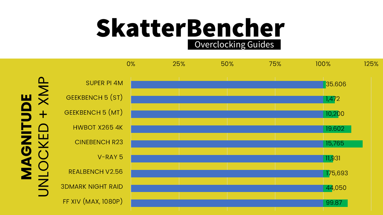
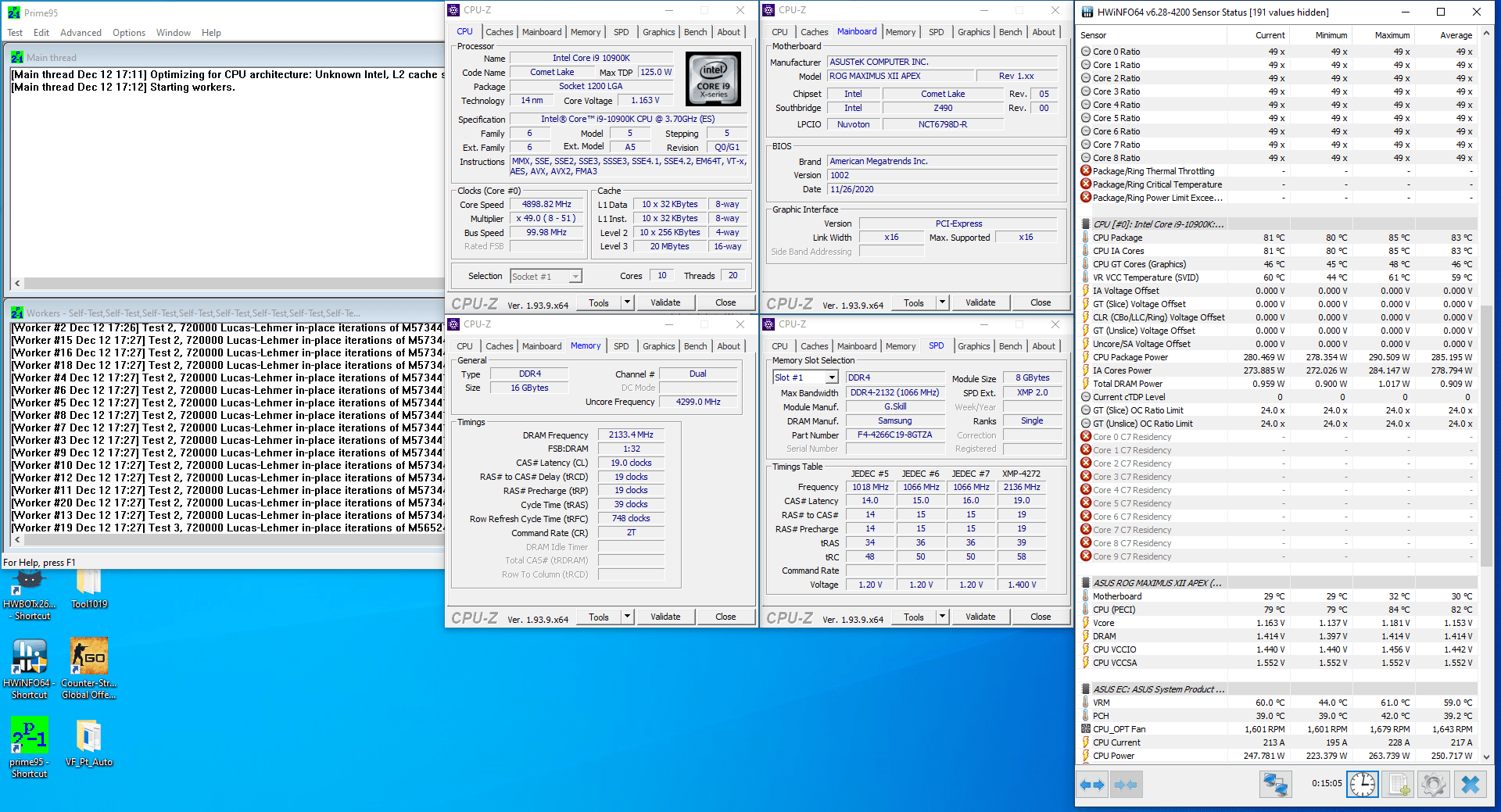
When running Prime95 small FFT with AVX enabled, the processor runs at 4.9GHz with 1.278V. The CPU power is around 285W and the average CPU temperature is 83 degrees centigrade.
Next up, manual overclocking.
Core i9-10900K: Magnitude Manual
Upon entering the bios:
- Enter the Extreme Tweaker menu
- Set Ai Overclock Tuner to XMP II
- Set ASUS MultiCore Enhancement to Enabled – Remove All Limits
- Set AVX Instruction Core Ratio Negative Offset to 2
- Set CPU Core Ratio to By Core Usage
- Enter the By Core Usage submenu
- Set Turbo Ratio Limit 0 to 55
- Set Turbo Ratio Cores 0 to 4
- Set Turbo Ratio Limit 1 to 54
- Set Turbo Ratio Cores 1 to 6
- Set Turbo Ratio Limit 2 to 53
- Set Turbo Ratio Cores 2 to 8
- Set Turbo Ratio Limit 3 to 52
- Set Turbo Ratio Cores 3 to 10
- Exit the By Core Usage submenu
- Set CPU Core/Cache Voltage to Adaptive Mode
- Set Additional Turbo Mode CPU Core Voltage to 1.525
- Go to the Advanced Menu
- Enter the CPU Configuration submenu
- Enter the CPU – Power Management Control submenu
- Ensure CPU C-states is set to enabled
Save and exit the bios.
We re-ran the benchmarks and got the following performance increase compared to stock.
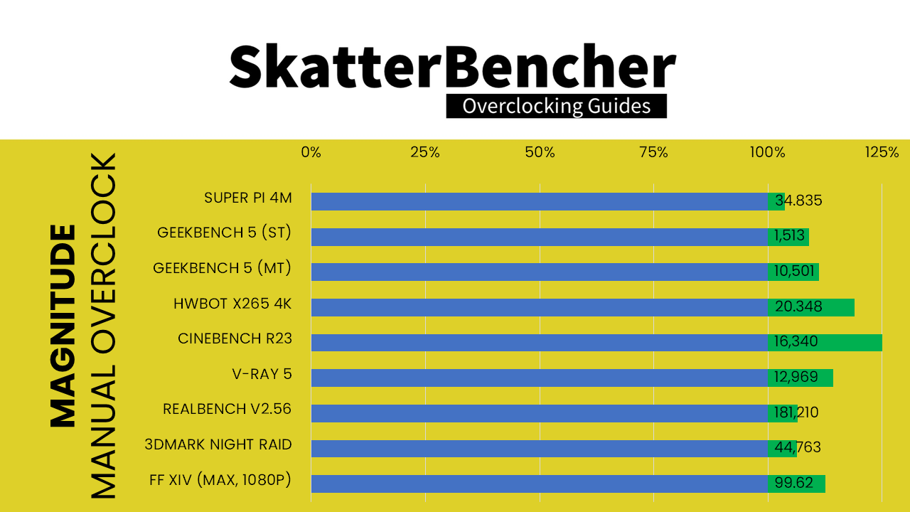
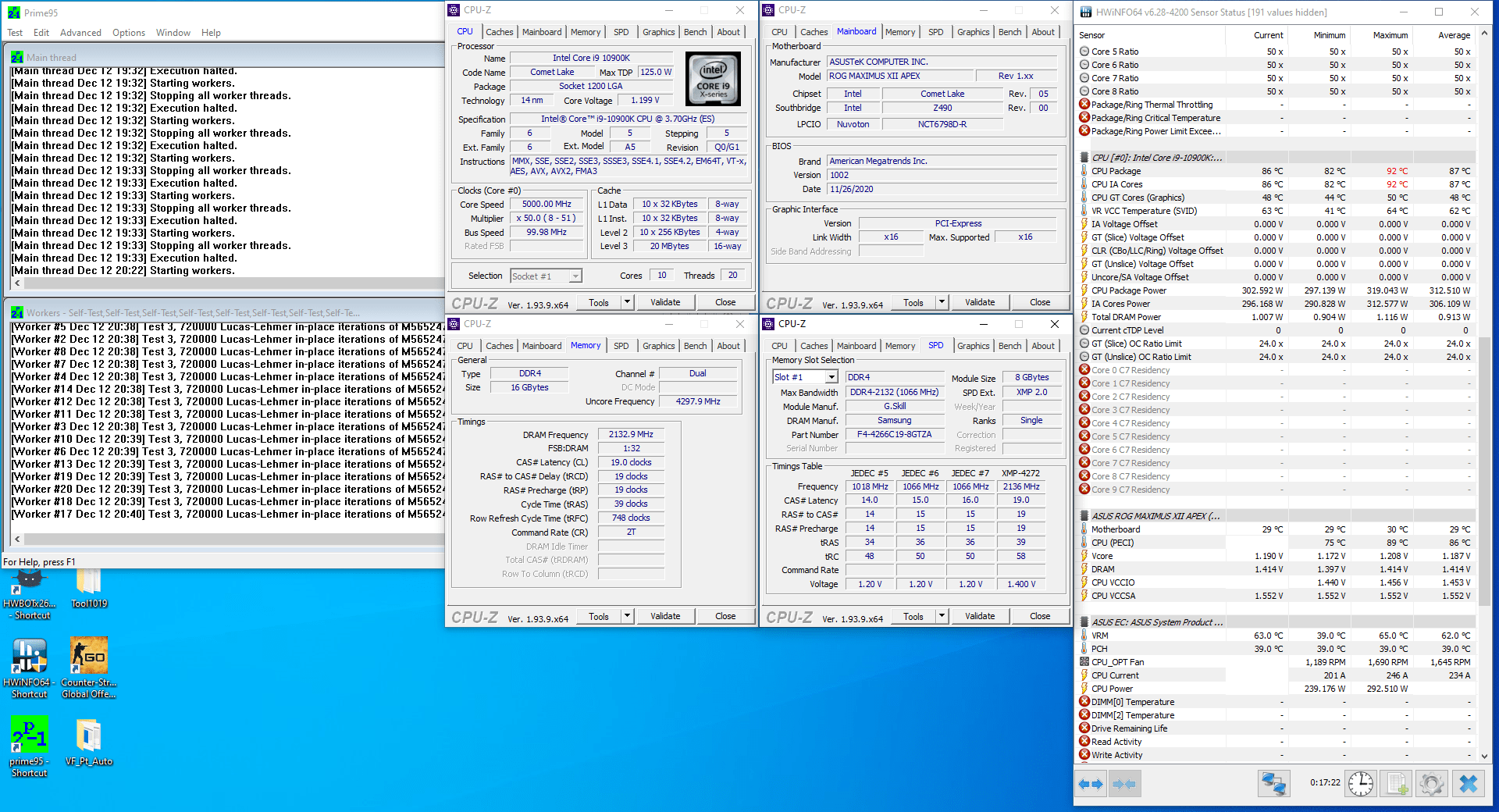
When running Prime95 small FFT with AVX enabled, the processor runs at 5.0GHz with 1.307V. The CPU power is around 312W and the average CPU temperature is 87 degrees centigrade.
Overclocking Using Intel Cryo Cooling Technology
In the second part of the overclocking journey we will overclock the CPU using the Intel Cryo Cooling technology. All our system components remain the same, but we swap out the cpu water block for the EK-QuantumX Delta TEC block.
We will test the Delta TEC in two modes: Cryo and Unregulated.
In Cryo mode, the Intel software ensures that the TEC never drops below the dew point. This avoids any form of condensation to occur.
In Unregulated mode, the TEC always runs at full power and thus the temperature will drop well below ambient. Without proper insulation you may face water droplets on your hardware so be careful. Make sure to follow the Delta TEC installation guide and take all the necessary precautions to avoid condensation.
If you’re also using the Maximus XII Apex, make note of the condensation sensor around the socket. While this feature is mostly targeted to the extreme overclockers using liquid nitrogen, it comes in handy with unregulated mode as well.
We will test the two modes in a variety of scenarios:
- Stock
- Unlocked
- ASUS TVB boost profiles
- Manual OC
Core i9-10900K: Cryo + Stock
Upon entering the bios:
- Enter the Extreme Tweaker menu
- Set ASUS MultiCore Enhancement to Disabled – Enforce All Limits
Then save and exit the bios. When in the Operating System, make sure to set the Intel Cryo Cooling to Cryo Mode.
We re-ran the benchmarks and got the following performance increase compared to default operation
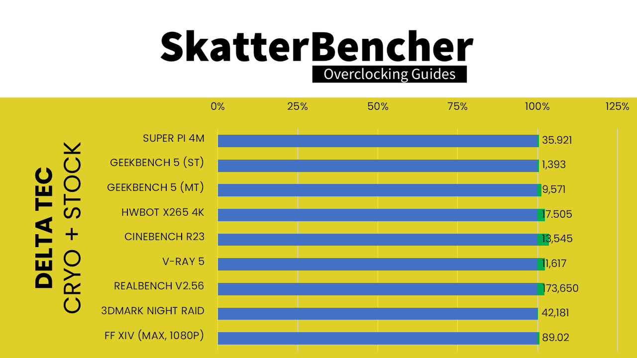
We can see that the performance is slightly higher in all benchmarks. This is due to the effect of enabling XMP as well as the Cryo Cooling ensuring better operating temperatures. The lower than regular water cooling temperatures help the CPU stay in Turbo for longer and enable to Thermal Velocity Boost for longer.
When running Prime95 small FFT with AVX enabled, the processor runs at 3.7GHz with 1.000V. The CPU power is around 121W and the average CPU temperature is 53 degrees centigrade.
Core i9-10900K: Cryo + Unlocked
Upon entering the bios:
- Enter the Extreme Tweaker menu
- Set Ai Overclock Tuner to XMP II
- Set ASUS MultiCore Enhancement to Enabled – Remove All Limits
Then save and exit the bios. When in the Operating System, make sure to set the Intel Cryo Cooling to Cryo Mode.
We re-ran the benchmarks and got the following performance increase compared to default operation
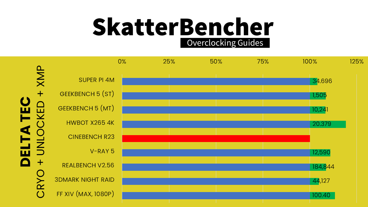
We can see that the performance continues to rise.
Comparing the Delta “unlocked” setting with the Magnitude “unlocked” setting, we can see that the performance is higher across all benchmarks except for Cinebench R23 where we didn’t get a score.
The performance increase can be attributed to the better temperatures which enables the CPU to stay in Thermal Velocity Boost for longer.
Cinebench R23 failed because of a thermal runaway situation. In case you didn’t know, Cinebench R23 introduces a 10 minute heat up before running the benchmark. That means the CPU is at full load for an extended period of time. It is during this heat up phase that we get a thermal runaway situation and overheating. That’s because, as we explained earlier in the video, the TEC is capable of handling up to 200W load. When we use unlocked turbo configuration, the load is around 280W.
When running Prime95 small FFT with AVX enabled, we face the same thermal runaway situation and the system crashes.
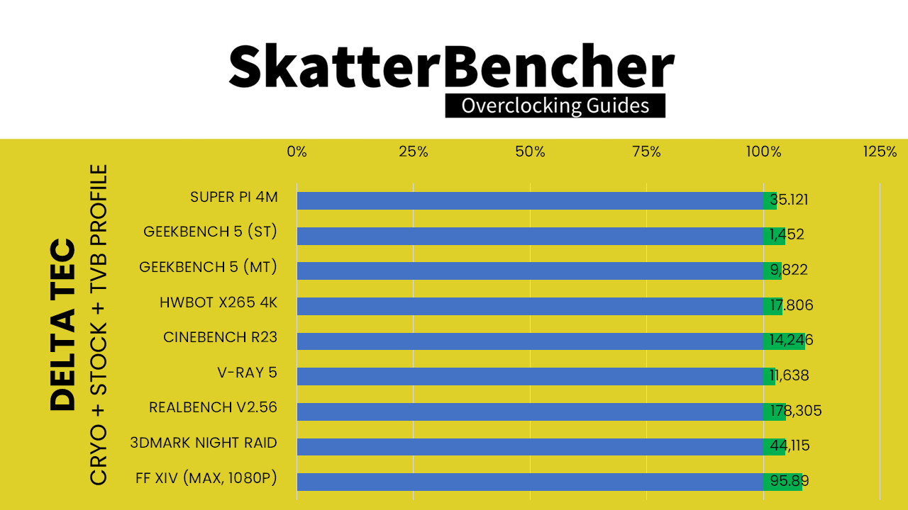
Core i9-10900K: Cryo + TVB Boost Profile
Now let’s start exploring the additional potential overclocking range enabled by the Cryo Cooling technology.
Our first step is to make use of the Thermal Velocity Boost profiles offered by the Maximus XII Apex motherboard. We will enable the +2 boost profile for each of the three overclocking configurations we tried with regular water cooling:
- Stock
- Unlocked
- Manual
For Stock comparison, upon entering the bios:
- Enter the Extreme Tweaker menu
- Set ASUS MultiCore Enhancement to Disabled – Enforce all limits
- Enter the Thermal Velocity Boost submenu
- Set Overclocking TVB to +2Boost Profile
Then save and exit the bios. When in the Operating System, make sure to set the Intel Cryo Cooling to Cryo Mode.
For unlocked comparison, upon entering the bios:
- Enter the Extreme Tweaker menu
- Set Ai Overclock Tuner to XMP II
- Set ASUS MultiCore Enhancement to Enabled – Remove All Limits
- Enter the Thermal Velocity Boost submenu
- Set Overclocking TVB to +2Boost Profile
Then save and exit the bios. When in the Operating System, make sure to set the Intel Cryo Cooling to Cryo Mode.
For manual overclock comparison, upon entering the bios:
- Enter the Extreme Tweaker menu
- Set Ai Overclock Tuner to XMP II
- Set ASUS MultiCore Enhancement to Enabled – Remove All Limits
- Set AVX Instruction Core Ratio Negative Offset to 2
- Set CPU Core Ratio to By Core Usage
- Enter the By Core Usage submenu
- Set Turbo Ratio Limit 0 to 55
- Set Turbo Ratio Cores 0 to 4
- Set Turbo Ratio Limit 1 to 54
- Set Turbo Ratio Cores 1 to 6
- Set Turbo Ratio Limit 2 to 53
- Set Turbo Ratio Cores 2 to 8
- Set Turbo Ratio Limit 3 to 52
- Set Turbo Ratio Cores 3 to 10
- Exit the By Core Usage submenu
- Enter the Thermal Velocity Boost submenu
- Set Overclocking TVB to +2Boost Profile
- Exit the Thermal Velocity Boost submenu
- Set CPU Core/Cache Voltage to Adaptive Mode
- Set Additional Turbo Mode CPU Core Voltage to 1.525
- Go to the Advanced Menu
- Enter the CPU Configuration submenu
- Enter the CPU – Power Management Control submenu
- Ensure CPU C-states is set to enabled
Then save and exit the bios. When in the Operating System, make sure to set the Intel Cryo Cooling to Cryo Mode.
We re-ran the benchmarks and got the following performance increase compared to default configuration
For Stock and +2 TVB Boost Profile in Cryo Mode
For Unlocked and +2 TVB Boost Profile in Cryo Mode
Cinebench R23 again failed because of a thermal runaway situation. In case you didn’t know, Cinebench R23 introduces a 10 minute heat up before running the benchmark. That means the CPU is at full load for an extended period of time. It is during this heat up phase that we get a thermal runaway situation and overheating. That’s because, as we explained earlier in the video, the TEC is capable of handling up to 200W load. When we use unlocked turbo configuration, the load is around 280W.
When running Prime95 small FFT with AVX enabled, we face the same thermal runaway situation and the system crashes.
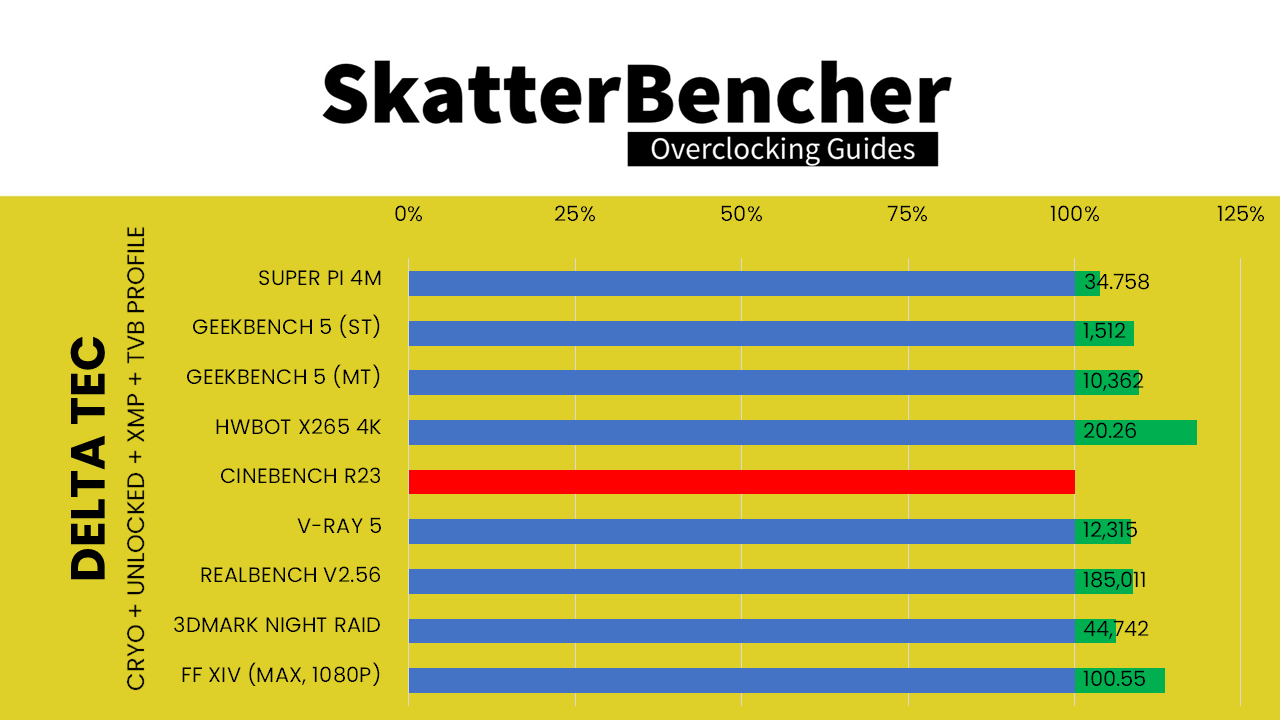
For Manual OC and +2 TVB Boost Profile in Cryo Mode

When running Prime95 small FFT with AVX enabled, the processor runs at 4166 MHz with 1.072V. The CPU power is around 171W and the average CPU temperature is 68 degrees centigrade.
Core i9-10900K: Cryo Unregulated + Manual
In our last step we will try out Unregulated Mode.
In Unregulated mode, the Delta TEC cools below ambient temperature with less protection from condensation. In this mode there will be condensation risk on the heatsink surfaces and surroundings due to the low temperature. It can cause system damage. This mode is indicated by a purple icon in the tray.
Please take all the necessary precautions when using Unregulated Mode. It may cause condensation which could result in electrical short circuit that can damage your parts.
We will compare two scenarios. The first scenario is simply using the same scenario as our Manual OC +2 TVB Boost Profile. The second scenario is our 6 GHz manual overclock configuration from the beginning of the video.
The settings for the Manual OC +2 TVB Boost Profile is as follows. Upon entering the bios:
- Enter the Extreme Tweaker menu
- Set Ai Overclock Tuner to XMP II
- Set ASUS MultiCore Enhancement to Enabled – Remove All Limits
- Set AVX Instruction Core Ratio Negative Offset to 2
- Set CPU Core Ratio to By Core Usage
- Enter the By Core Usage submenu
- Set Turbo Ratio Limit 0 to 55
- Set Turbo Ratio Cores 0 to 4
- Set Turbo Ratio Limit 1 to 52
- Set Turbo Ratio Cores 1 to 6
- Set Turbo Ratio Limit 2 to 51
- Set Turbo Ratio Cores 2 to 8
- Set Turbo Ratio Limit 3 to 50
- Set Turbo Ratio Cores 3 to 10
- Exit the By Core Usage submenu
- Enter the Thermal Velocity Boost submenu
- Set Overclocking TVB to +2Boost Profile
- Exit the Thermal Velocity Boost submenu
- Set CPU Core/Cache Voltage to Adaptive Mode
- Set Additional Turbo Mode CPU Core Voltage to 1.525
- Go to the Advanced Menu
- Enter the CPU Configuration submenu
- Enter the CPU – Power Management Control submenu
- Ensure CPU C-states is set to enabled
Then save and exit the bios. When in the Operating System, make sure to set the Intel Cryo Cooling to Unregulated Mode.
The settings for our 6GHz manual overclock are as follows. Upon entering the BIOS:
- Enter the Extreme Tweaker menu
- Set Ai Overclock Tuner to XMP II
- Set ASUS MultiCore Enhancement to Enabled – Remove All Limits
- Set CPU Core Ratio to By Core Usage
- Enter the By Core Usage submenu
- Set Turbo Ratio Limit 0 to 60
- Set Turbo Ratio Cores 0 to 4
- Set Turbo Ratio Limit 1 to 54
- Set Turbo Ratio Cores 1 to 6
- Set Turbo Ratio Limit 2 to 52
- Set Turbo Ratio Cores 2 to 10
- Exit the By Core Usage submenu
- Enter the Thermal Velocity Boost submenu
- Set Overclocking TVB to Enabled
- Set 1-Core to 10-Core Active to Enabled
- Then for 1-Core to 10-Core set Temperature A, Ratio Offset, and Temperature B to the following:
- 1-Core: 10, 3, 55
- 2-Core: 10, 3, 51
- 3-Core: 10, 4, 47
- 4-Core: 10, 4, 43
- 5-Core: 58, 1, 68
- 6-Core: 54, 1, 64
- 7-Core: 62, 1, 72
- 8-Core: 58, 1, 68
- 9-Core: 54, 1, 64
- 10-Core: 50, 1, 60
- Exit the Thermal Velocity Boost submenu
- Enter the Tweaker’s Paradise submenu
- Set Internal PLL Voltage to 0.9
- Set Ring PLL Voltage to 0.9
- Set PLL Bandwidth to Level 1
- Set Eventual PLL Termination Voltage to 1.05
- Exit the Tweaker’s Paradise submenu
- Enter the AI Features submenu
- Set Package Temperature Threshold to 85
- Set Regulate Frequency by above Threshold to Enabled
- Exit the AI Features submenu
- Set CPU Core/Cache Voltage to Adaptive Mode
- Set Additional Turbo Mode CPU Core Voltage to 1.550
- Go to the Advanced Menu
- Enter the CPU Configuration submenu
- Enter the CPU – Power Management Control submenu
- Ensure CPU C-states is set to enabled
- Go to the Monitor menu
- Enter the Q-Fan Configuration submenu
- Enter the Chassis Fan Configuration submenu
- Set Chassis Fan Q-Fan Control to Auto
- Set Chassis Fan Q-Fan Source to T_Sensor
- Set Chassis Fan 2 Profile to Manual
- Set the upper temperature to 50
- Set the max duty cycle to 100%
- Set the middle temperature to 30
- Set the middle duty cycle to 60
- Set the lower temperature to 25
- Set the min duty cycle to 20%
- Enter the boot menu
- Set Wait for ‘F1’ If Error to Disabled
Save and exit the bios. When in the Operating System, make sure to set the Intel Cryo Cooling to Unregulated Mode.
We re-ran the benchmarks and got the following performance increase compared to default configuration:
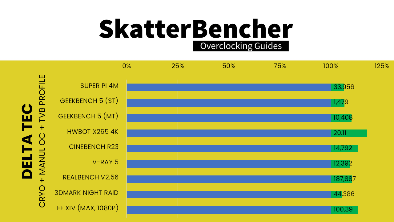
For Manual OC and +2 TVB Boost Profile in Unregulated Mode

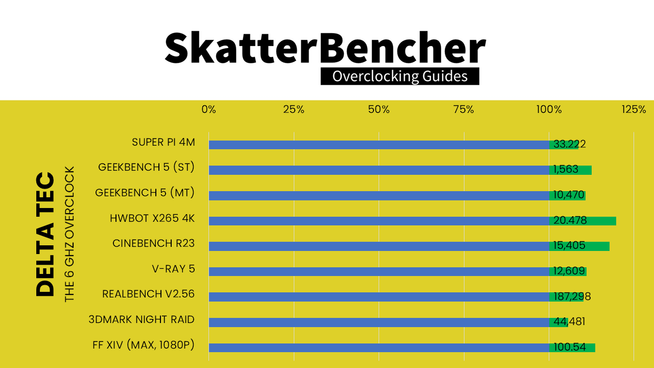
For Manual OC and Manual Thermal Velocity Boost in Unregulated Mode
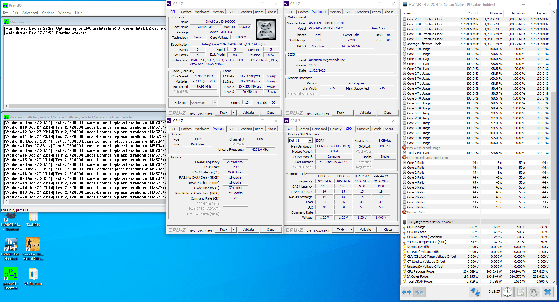
When running Prime95 small FFT with AVX enabled, the processor runs at 4400 MHz with XXX V. The CPU power is around 200W and the average CPU temperature is 85 degrees centigrade.
Performance Overview
Before we get to the conclusive thoughts, let’s compare the performance results of all different overclocks.
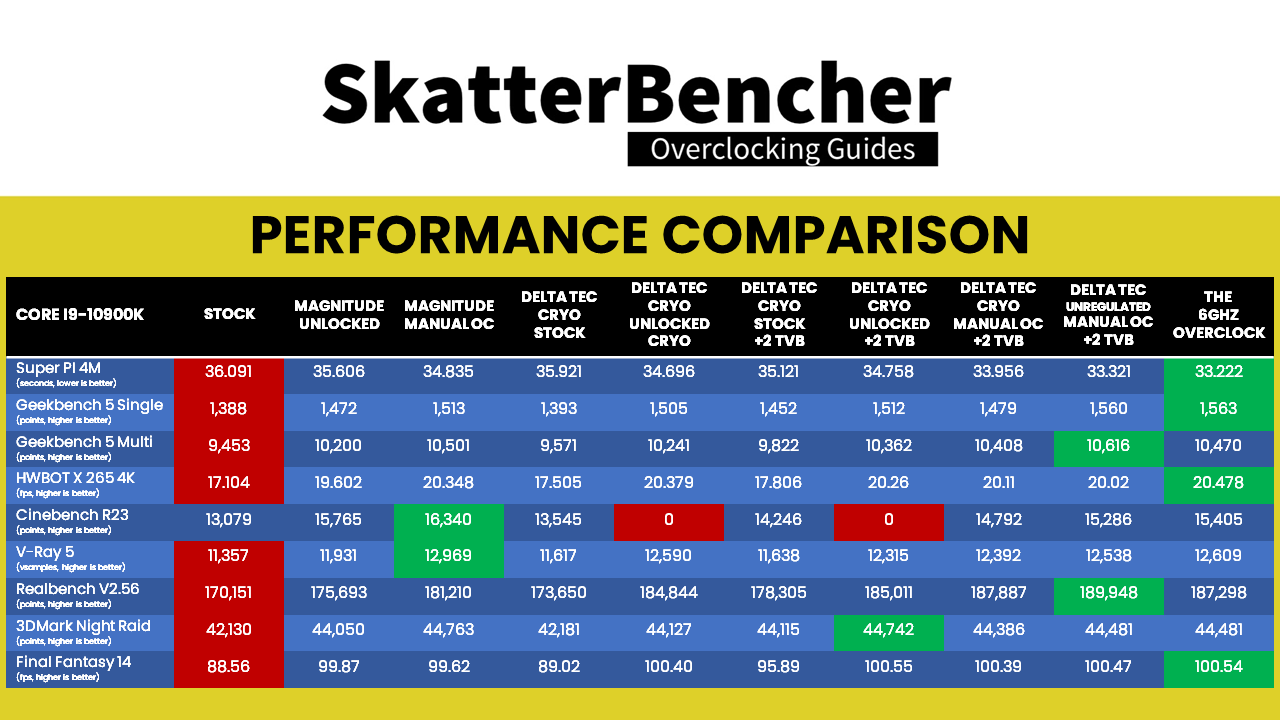
Looking at the pure benchmark score comparison, we notice a couple of things.
First, in heavy multi-threaded benchmark applications like Cinebench R23 and V-Ray 5 regular high-end custom loop water cooling comes out on top. That’s because the cooling system is capable of handling power consumption loads over 200W with ease. The TEC is limited to 200W so when a workload comes by that exceeds this, either the CPU will start heating up faster, reducing its frequency faster, or not work altogether.
Cinebench R23 in particular is a tough nut to crack. As mentioned before, if we don’t either limit the long duration maximum power or have the system target a specific temperature, the system will not pass the benchmark
Second, our maxed out overclock using unregulated mode has the most wins across all benchmarks and is particularly strong in lightly threaded workloads like SuperPI or Geekbench 5. That said, the performance difference with using one of ASUS’ TVB boost profiles is not that significant.
However, all things considered it looks like a well-tuned system with Cryo Cooling will definitely provide more performance than high-end custom loop water cooling.
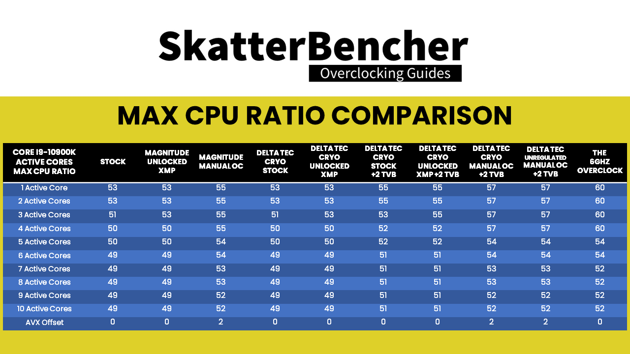
Looking at the maximum CPU ratio table you can see why the performance difference across all Cryo cooled systems isn’t that large. Without manual tuning we already get up to 51X for a couple of cores and up to 51X for 10 cores.
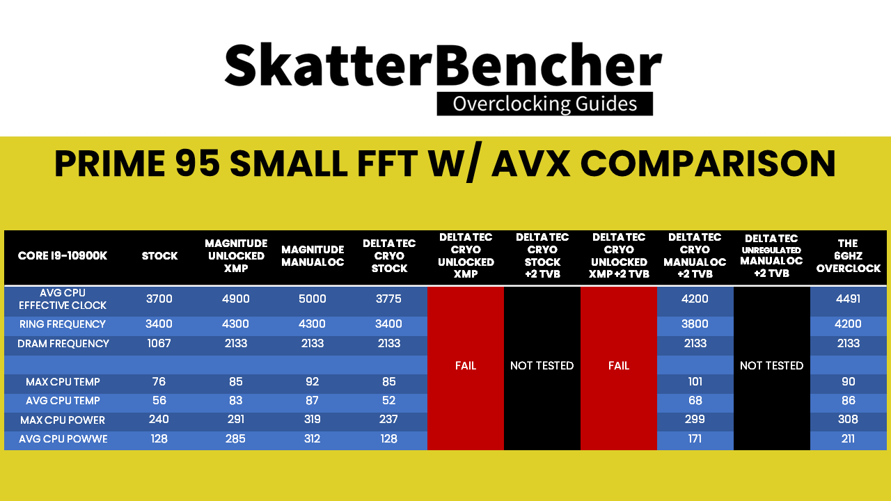
Looking at the Prime 95 SmallFFT with AVX comparison, we note again that a configuration with power limits unlocked will fail long-term stability tests unless we set other constraints. We achieved about 4.5GHz stable with our manual maxed out system. While that’s still well above the 3.7 GHz at stock, it is well-below the 5 GHz we can achieve with high-end custom loop water cooling.
Conclusion
Alright, let’s wrap this up.
I really enjoyed tinkering with the Intel Cryo Cooling Technology. Even though it took me several weeks to figure out all the challenges and workarounds, I feel very satisfied with the final result. It’s especially cool to see so many different technologies and features work together to squeeze more performance out of the CPU.
Looking at the final overclocking and performance result, we can highlight the following.
First, it’s pretty awesome that the Intel Cryo Cooling Technology offers the tools to get a real-world 6 GHz system. Admittedly, it doesn’t run games or any other applications at this speed. But even seeing it idle in Windows at this frequency is very exciting.
Second, we can see some additional performance benefit in lightly threaded workloads from the higher frequencies reaching up to 5.7GHz. That said, we must also acknowledge that the Core i9-10900K is already a very well-tuned beast with its maximum boost frequency of 5.3 GHz. The actual time the Cryo system is running at higher frequencies than the default configuration isn’t much. So we’re really talking about marginal performance gains.
Thirdly, the multi-threaded performance is lower than what we see from a well-tuned system with high-end custom loop water cooling. That is of course to be expected since the power consumption can easily exceed 300W on a highly overclocked i9-10900K running a very demanding workload. This is far above the 200W maximum capability of the TEC integrated in the EK-QuantumX Delta. That said, with the right BIOS settings and options we can mitigate this problem relatively well. Our maximum stable overclock in Prime 95 SmallFFT with AVX enabled is 5 GHz with custom loop water cooling and 4500 MHz with our TEC system. That’s still much, much higher than the 3700 MHz we get at stock.
To sum up my experience, I’d say this was a very interesting overclocking journey. The Intel Cryo Cooling Technology had me hooked on tuning for a couple of weeks and it feels great to find news ways to extract more performance.
Overall, I’d say this is quite a solid implementation for the first generation of Intel Cryo Cooling Technology. I think it was smart of Intel to work together with industry partners like EK and Cooler Master as well as enable the motherboard partners to bring a complete package to user which includes the software control, the cooling equipment, and the motherboard BIOS support.
Of course there is still lots of room for improvement but I cannot wait to see how future iterations of Cryo Cooling will help enthusiasts unlock even more performance.
That’s all for today. I hope you enjoyed the video and our deep dive in the Intel Cryo Cooling Technology. I promise you next videos will be back to our regular format. If you have any questions or comments, feel free to drop them in the comment section below.
See you next time
SkatterBencher #28: Intel UHD Graphics 750 Overclocked to 1750 MHz - SkatterBencher
[…] EK-QuantumX Delta TEC is not new. I’ve used the Delta TEC in two previous videos: once to get a Core i9-10900K up to 6 GHz and once to get the Core i9-11900K up to 5.6GHz. That was with the 1st gen Delta […]
ElmorLabs EFC Easy Fan Controller | SkatterBencher
[…] we have looked at Intel Cryo Cooling a couple of times now. We used Intel Cryo Cooling to get a 6 GHz Comet Lake system and a 5.6 GHz Rocket Lake […]
SkatterBencher #25: Intel Core i9-11900K Cryo Overclocked to 5600 MHz | SkatterBencher
[…] also explored the Cryo Cooling technology, OCTVB and the EK Delta Tec in a previous article using the Core i9-10900K Comet Lake processor. While that video was a lot of fun to do and contains a lot of information on how to set up your […]
SkatterBencher #21: Intel Core i9-11900K Overclocked to 5500 MHz | SkatterBencher
[…] The Intel Core i9-11900K is the flagship processor of Intel’s 11th generation Core CPUs for desktop codenamed Rocket Lake. It is the successor of the Core i9-10900K which we overclocked twice before: once with water cooling and once with TEC cooling. […]